1. INTRODUCTION
Although originally designed to provide position, velocity and timing for land, maritime and air applications, Global Navigation Satellite Systems (GNSS) have also been adopted for use in Low Earth Orbit (LEO) space applications such as for attitude determination, time synchronisation, orbit determination, and absolute and relative position determination. Indeed, a GNSS receiver can maximise the autonomy of a spacecraft and reduce the burden and the costs of network operations (Miller, Reference Miller2011). For the same reasons, the use of GNSS is also very appealing for applications at higher altitudes, such as for Medium Earth Orbit (MEO), Geostationary Orbit (GEO), and Highly Elliptical Orbit (HEO) missions, and even for Moon Transfer Orbits (MTOs), which are the focus of this paper. In particular, the recent stronger interest in lunar exploration in the scientific community has pushed companies and institutions to investigate the use of GNSS as the navigation system for Moon missions, as it would significantly reduce the operating costs.
The first space-borne GNSS receiver flew on board the Landsat 4 spacecraft in 1982 (Bauer et al., Reference Bauer, Moreau, Dahle-Melsaether, Petrofski, Stanton, Thomason, Harris, Sena and Parker Temple2006), while the first use of GNSS above the Global Positioning System (GPS) constellation altitude up to the GEO altitude was made in 1997 during different experiments on board the Equator-S and the DSCS-3 (Defense Satellite Communications 3) satellites, as published in Powell et al. (Reference Powell, Martzen, Sedlacek, Chao, Silva, Brown and Belle1999) and Balbach et al. (Reference Balbach, Eissfeller, Hein, Enderle, Schmidhuber and Lemke1998). In more recent papers (Capuano et al., Reference Capuano, Botteron and Farine2013; Reference Capuano, Botteron, Wang, Tian, Leclère and Farine2014; Reference Capuano, Botteron, Leclere, Tian, Yanguang and Farine2015; Silva et al., Reference Silva, Lopes, Peres, Silva, Ospina, Cichocki, Dovis, Musumeci, Serant, Calmettes, Pessina and Perelló2013; Palmerini et al., Reference Palmerini, Sabatini and Perrotta2009), the use of GNSS as a navigation system to reach the Moon has been analysed. In Capuano et al. (Reference Capuano, Botteron, Wang, Tian, Leclère and Farine2014) we have shown some preliminary results from the development undertaken in our laboratory of a proof of concept prototype Field-Programmable Gate Array (FPGA)-based GPS receiver for lunar missions.
A GNSS unfiltered navigation solution is approximately as accurate in LEO as on the Earth; above the GNSS constellation on the way to the Moon, however, the accuracy of the system will decrease. Since the GNSS transmitters point towards the Earth, the signal received by a spacecraft above the GNSS constellation will only come from the spill over around the Earth of the signals transmitted from the main lobe or from one of the side lobes of the satellite's antennae patterns. In any case, the received power at the receiver position will be considerably lower than as received by a user on the Earth's surface. This is partly due to the propagation range between the receiver and the GPS satellites that is much higher (in most of the orbit) than for an Earth-based user resulting in extra free space loss attenuation. Moreover if signals are tracked from one of the side lobes of the GNSS antenna pattern the transmitted power is much lower than that transmitted by the main lobe (Unwin et al., Reference Unwin, Van Steenwijk, Blunt, Hashida, Kowaltschek and Nowak2013). As a result, the number of visible satellites that can be tracked above the GNSS constellation drops dramatically and in some cases it may not be possible to compute a navigation solution (i.e., when there are fewer than four visible satellites). In addition, the poor relative geometry of the GNSS satellites at very high altitude can drastically reduce the navigation solution accuracy, due to the very limited region in the field of view where the GNSS satellites can be observed. This results in an increased Geometric Dilution Of Precision (GDOP) as compared to an Earth user.
On the other hand, a spacecraft is constrained to move along a certain trajectory by the orbital forces acting on it. For these reasons the use of orbital filters, which fuse GNSS observations and the prediction of the space dynamics leads to better solutions than that achieved by a stand-alone GPS receiver. Orbital filters are widely used to improve the accuracy of the navigation solution provided by GNSS receivers. This is documented in Chiaradia et al. (Reference Chiaradia, Gill, Montenbruck, Kuga and Prado2000), Habib (Reference Habib2013), Pardal et al. (Reference Pardal, Kuga and Vilhena de Moraes2009) and many others. All of them use a Kalman Filter estimator for the positioning of a satellite in LEO.
In this research, we describe the implementation of GNSS-based orbital filter for lunar missions that uses an adaptive Extended Kalman Filter (EKF) tuned along the MTO as function of the GNSS measurements. Firstly, we consider the use of the GPS L1 Coarse/Acquisition (C/A) signals by modelling the observables as they would be provided by the space-borne WeakHEO receiver prototype (Capuano et al., Reference Capuano, Botteron, Wang, Tian, Leclère and Farine2014), an FPGA-based receiver for lunar missions under development in our laboratory. In addition to considering the case of GPS L1 C/A only, we also show the performance achievable by using a dual constellation receiver that processes signals from both GPS and from Galileo. The achieved navigation performance provided by filtering the GNSS observations is compared to the performance obtained by using the corresponding non-filtered GNSS least square solution, whose accuracy decreases as the distance from the GNSS constellation increases, becoming almost meaningless when the spacecraft reaches the Moon altitude. Furthermore, we also report the Doppler shift and Doppler rate estimation accuracy of the filter that can strongly aid the GNSS signal processing module.
2. REFERENCE RECEIVER TRAJECTORY
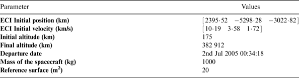
As mentioned in the introduction, the reference trajectory of the receiver is a MTO. The initial conditions of the MTO in the Earth Centred Inertial (ECI) reference frame, the starting date, and the characteristics of the spacecraft assumed in the performed simulations are shown in Table 1. The motion of the receiver is propagated by the Spirent simulation software SimGen, which models several perturbing accelerations, such as the Earth gravitational spherical harmonics up to the 21st degree and 21st order, the effect of atmospheric drag and Solar Radiation Pressure (SRP), and the third body perturbation due to both the Sun and the Moon (Spirent, 2012).
Table 1. Initial conditions for the MTO, spacecraft characteristics and final altitude before starting the injection into selenocentric orbit manoeuvre.

Figure 1 illustrates the spacecraft trajectory for the entire lunar mission, together with the GPS constellation, that starts from the launch and ends with a selenocentric orbit. The considered trajectory includes only the MTO, which is identified by the light blue orbit portion.
Figure 1. Considered lunar mission: the MTO is the curve in light blue (image generated by using STK).
Figure 2 displays the relation between the altitude (of the spacecraft and of the GPS satellites) and the time of the full considered MTO. We can see that for most of the transfer orbit the spacecraft is above the GPS constellation.
Figure 2. Relation between altitude and time during the considered MTO. The average distance between an Earth receiver and the GPS satellites at zenith is approximately 20,200 km, but for 99% of the travel time of a receiver flying in the defined MTO, this distance is larger.
3. GNSS OBSERVATIONS MODEL
In order to reproduce correctly the GNSS signal powers at the receiver, the SimGen software of our Spirent 8000 simulator models the gain pattern of both the transmitting and receiving antennas. This is required to differentiate the power level of the signals coming from the side lobes of the transmitting antennae from the ones transmitted from the main lobe.
Information about the transmitting antenna pattern of different GPS signals and blocks are reported in the literature: e.g. for the Block IIA in Czopek and Shollenberger (Reference Czopek and Shollenberger1993), IIR in Wu (Reference Wu2002) and IIF in Erker et al. (Reference Erker, Tholert, Furthner and Meurer2009). Unfortunately, less detail can be found for Galileo; indeed only the gain at boresight and at the end of the coverage of the transmitting antenna of the four Galileo In-Orbit Validation (IOV) satellites are provided in Arenas et al. (Reference Arenas, Monjas, Montesano, Montesano, Mangenot and Salghetti2011). Given the missing detailed information about the transmitting antenna patterns for both constellations, we choose for this study that focuses on the orbital filtering performances (and not specifically on the differences between antenna pattern of different blocks and constellations) to adopt the GPS transmitter antenna pattern from Block II-A (illustrated in Figure 3 as defined in Czopek and Shollenberger (Reference Czopek and Shollenberger1993) and provided by Spirent (2012) to model all the transmitters for all the considered satellite signals. This simplifying assumption, reasonable for the goal of this research, should be considered as an analysis limitation for the reader who is specifically interested in the difference between the performance of the signals transmitted by the side lobes of different GPS and Galileo blocks. In addition, we assumed that the L1 C/A signals are transmitted by 30 GPS satellites and the E5 (E5aQ + E5bQ) signals are transmitted by all the nominal 27 Galileo satellites.
Figure 3. GPS Transmitter Antenna Pattern used to simulate the antenna pattern of all considered GNSS satellites (based on Czopek and Shollenberger (Reference Czopek and Shollenberger1993) for Block II-A). The boresight is at 90°. The gain is normalised to 0 dB at boresight.
Regarding the receiving antenna, following Capuano et al. (Reference Capuano, Botteron, Wang, Tian, Leclère and Farine2014; Reference Capuano, Botteron, Leclere, Tian, Yanguang and Farine2015), an antenna gain at the receiver of 10 dBi is assumed. Such gain value during the whole trajectory may be obtained placing more than one receiver antenna on different faces of the spacecraft (in such a way that at least one points to the GNSS satellites), as assumed in Capuano et al. (Reference Capuano, Botteron, Wang, Tian, Leclère and Farine2014; Reference Capuano, Botteron, Leclere, Tian, Yanguang and Farine2015) and Palmerini et al. (Reference Palmerini, Sabatini and Perrotta2009), or by using a steerable directive antenna (Litva, Reference Litva1996).
In order to compute for each satellite a realistic signal power P r,k at the receiver, where k denotes the satellite number, SimGen simulates for each satellite the received GNSS signal strength using the following equation (Spirent, 2012):
 $$P_{r,k} = P_{ICD} + O_G + 20 \times \log _{10} \left( {\displaystyle{{R_0} \over {R_k}}} \right) - L_{tx} - L_{rx} $$
where P ICD is the guaranteed minimum signal level on the Earth as given in GNSS Signal In Space Interface Control Documents (SIS ICDs). O G is the “Global Offset”. A value of +3 dB has been used to match the performance obtained when using the simulator (transmitting P ICD) with the performance obtained when real signals are received. Since the transmitted signal powers are typically from 1 to 5 dB higher than the minimum received signal power value (Kaplan and Hegarty, Reference Kaplan and Hegarty2006), an intermediate value of 3 dB has been chosen for both constellations. R 0 is the reference range used for inverse-square variation calculation and equal to the range from an Earth-based receiver to the GNSS satellite at zero elevation. R k is the range from the kth GNSS satellite to the receiver. L tx, k is the gain from the kth GNSS satellite transmit antenna in the direction of the receiver that takes into account the radiation pattern of the antenna. Finally, L rx, k is the gain from the receiver antenna in the direction of the kth GNSS satellite which in our paper has been considered as constant and equal to 10 dBi.
Since the simulator only supports 12 channels for the GPS constellation and 12 channels for the Galileo constellation, a selection of the simulated satellites are performed by SimGen. For a high orbit mission (where the signals are very weak), the 12 simulated satellites from each constellation are those corresponding to the 12 strongest received signals (Spirent, 2012).
As stated in our previous studies (Capuano et al., Reference Capuano, Botteron, Wang, Tian, Leclère and Farine2014; Reference Capuano, Botteron, Leclere, Tian, Yanguang and Farine2015), for the considered MTO, the minimum receiver sensitivity required to acquire and track at least the four most powerful signals from the GPS satellites simultaneously is about −168 dBm (at least four satellites are required to compute the navigation solution). Therefore, by considering a receiver antenna gain of 10 dBi, we are considering a receiver sensitivity of −159 dBm, taking a 1 dB margin. The received power value in dBm P r can also be expressed in terms of carrier-to-noise ratio C/N 0, which is given by the following equation, considering a front-end noise figure of 2 dB and assuming an effective antenna temperature of 130 K (Van Diggelen, Reference Van Diggelen2009).
 $$C/N_0 = P_r + 174$$
Using Equation (2) the sensitivity value of −159 dBm corresponds to 15 dB-Hz.
3.1. GPS observations
For the GPS L1 C/A signals, we have used P ICD = −128·5 dBm according to (Anon., 2011).
In our simulations, the pseudorange and pseudorange rate observables from the visible signals are modelled according to the GPS theory presented in Kaplan and Hegarty (Reference Kaplan and Hegarty2006) as follows:
 $$\rho = \sqrt {\left( {x_{sat} - x_u} \right)^2 + \left( {y_{sat} - y_u} \right)^2 + \left( {z_{sat} - z_u} \right)^2} + b + errors_\rho $$
 $$\dot \rho = \left( {{\bi v}_{{\bi sat}} - {\bi v}_{\bi u}} \right) \cdot {\bi a} + \dot b + errors_{\dot \rho} $$
 In Equation (3),  $\left[ {\matrix{ {x_{sat}} & {y_{sat}} & {z_{sat}} \cr}} \right]^T $ denotes the position's vector of the GPS satellite that is transmitting the signal, $\left[ {\matrix{ {x_u} & {y_u} & {z_u} \cr}} \right]^T $ is the user's position vector, and b is the receiver's clock offset in metres. We assumed an arbitrary initial clock offset of 10 km. In Equation (4), vsat and vu are, respectively, the velocity vector of the transmitting GPS satellite and of the spacecraft, $\dot b$ represents the clock's drift expressed as range-rate bias (in m/s), and a is the Line-Of-Sight (LOS) vector from the user to the GPS satellite. A clock drift of $\dot b = 100\; {\rm m}/{\rm s}$ has been considered (note that this is a conservative value as a more precise clock such as an Oven Controlled Oscillator (OCXO) can achieve a frequency variation of about one part in 1011 over a second, corresponding to a range-rate bias on the order of 3 m/s (Groves, Reference Groves2013). Both the position and velocity of the GPS satellites and of the receiver are provided by Spirent's simulator.
Pseudorange observables are affected by systematic and non-systematic errors denoted as errors ρ in Equation (3), which can be classified into: Signal-in-Space Ranging Error (SISRE), which includes satellite clock error and broadcast satellite ephemeris error; atmospheric delay; multipath effect and receiver error.
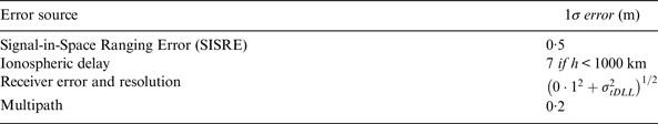
According to Kaplan and Hegarty (Reference Kaplan and Hegarty2006), these errors can be assumed as white Gaussian noise with a certain standard deviation (although this is not strictly true it is sufficient for this analysis), as summarised in Table 2 and described below. The overall error that affects pseudoranges can thus be described by the user equivalent range error (σ UERE), defined as the root sum square of the different range error contributions in Table 2.
Table 2. GPS L1 C/A code error budget. h denotes the altitude of the spacecraft, and σtDLL denotes the DLL (Delay Lock Loop) code thermal noise jitter that depends on the received C/No
According to McDonald and Hegarty (Reference McDonald and Hegarty2000), for the GPS constellation we have considered a value of 0·5 m for the transmitter's clock and broadcast ephemeris errors often described as Signal-in-Space Ranging Error (SISRE) (Engel, Reference Engel2008).
The residual error on pseudorange measurements due to ionospheric effect is considered only when the spacecraft is inside the atmosphere. When the receiver is located above 1000 km, which is the edge of the ionosphere (Kaplan and Hegarty, Reference Kaplan and Hegarty2006), the GPS signals may cross the ionosphere only when they are transmitted by satellites which are on the other side of the Earth. In this case the ionosphere layer could be crossed twice with a consequently greater delay of the signals. However when the receiver is far enough from the Earth (i.e. in most parts of the MTO up to 384 400 km), it rarely receives signals that, transmitted from GNSS satellites at MEO altitudes of roughly 19,000–23,000 km altitude, cross the ~19–23 times smaller ionosphere layer. Therefore, in this study, the ionosphere delay residual of 7 m (Kaplan and Hegarty, Reference Kaplan and Hegarty2006) is only modelled when the receiver is below the altitude of the ionosphere, while when above, pseudoranges from satellites whose line of sight crosses the ionosphere (and thus the troposphere situated below) are discarded. Furthermore, in this simulation, when the receiver is below the highest bound of the ionosphere the signals never pass through the troposphere, so the troposphere is neglected.
Typical modern Earth GNSS receivers have values for the pseudorange noise and resolution error of approximately 0·1 m or less (1σ) in nominal conditions (Kaplan and Hegarty, Reference Kaplan and Hegarty2006). However, for very weak signals such as those seen when operating above the GPS constellation, the noise value can be much higher. The DLL (Delay Lock Loop) code thermal noise jitter σtDLL increases as the receiver carrier to noise density of the signal C/N 0 decreases (Kaplan and Hegarty, Reference Kaplan and Hegarty2006). For this reason we have modelled the σtDLL as a function of the C/N 0 and we have added it to the constant value of 0·1 m that conservatively takes into account other possible error sources. For Binary Phase Shift Keying (BPSK) modulations (e.g., GPS L1 C/A and Galileo E5 individually filtered components), when a non-coherent power DLL discriminator is used, a general expression for the thermal noise code tracking jitter is according to Betz and Kolodziejski (Reference Betz and Kolodziejski2000):
 $$\eqalign{& {\rm \sigma} _{{\rm tDLL}} \cong \cr & \left\{ \matrix{\sqrt {\displaystyle{{B_n} \over {2\displaystyle{C \over {N_0}}}} D\left[ {1 + \displaystyle{2 \over {T\displaystyle{C \over {N_0}} (2 - D)}}} \right]}, \, D \ge \displaystyle{{\pi R_c} \over {B_{\,fe}}} \hfill \cr \sqrt {\displaystyle{{B_n} \over {2\displaystyle{C \over {N_0}}}} \left( {\displaystyle{1 \over {B_{\,fe} T_c}}} \right)\left[ {1 + \displaystyle{1 \over {T\displaystyle{C \over {N_0}}}}} \right]}, \, D \le \displaystyle{{R_c} \over {B_{\,fe}}} \quad \quad \quad [chips] \hfill \cr \sqrt {\displaystyle{{B_n} \over {2\displaystyle{C \over {N_0}}}} \left[ {\left( {\displaystyle{1 \over {B_{\,fe} T_c}}} \right) + \displaystyle{{B_{\,fe} T_c} \over {\pi - 1}}\left( {D - \displaystyle{1 \over {B_{\,fe} T_c}}} \right)^2} \right]\left[ {1 + \displaystyle{2 \over {T\displaystyle{C \over {N_0}} (2 - D)}}} \right]}, \quad \displaystyle{{R_c} \over {B_{\,fe}}} \lt D \lt \displaystyle{{\pi R_c} \over {B_{\,fe}}} \hfill} \right.} $$
where B n is the code loop noise bandwidth expressed in Hz; D is the early-to-late correlator spacing in units of chips; T is the coherent integration time in seconds; B fe is the double-sided front-end bandwidth in Hz; R c = 1/T c is the chipping rate expressed in chips/s and C/N 0 is the carrier to noise ratio in dB-Hz. In our simulations, we have assumed a B n = 0·5 Hz, D = 0·3 chips, T = 20 ms, B fe = 26 MHz, R c = 1/T c = 1·023 Mchip/s (values chosen in order to match the current parameters setting of the space-borne GPS-based WeakHEO receiver prototype under development in our laboratory (Capuano et al., Reference Capuano, Botteron, Wang, Tian, Leclère and Farine2014)).
Modern GNSS receivers obtain pseudorange rate observables by evaluating the Doppler shift of the received frequency from the transmitted one. As stated in Kaplan and Hegarty (Reference Kaplan and Hegarty2006), pseudorange rates may be computed simply by multiplying the Doppler shift with the wavelength of the signal carrier. This is done here; hence, the pseudorange rate error  $errors_{\dot \rho} $ in Equation (4) is due to the error in the frequency estimation. In particular, Doppler frequency estimations (and then pseudorange rates) are also affected by thermal noise, which is assumed here as the only source of error. According to (Borio et al., Reference Borio, Sokolova and Lachapelle2010) and assuming a standard PLL (Phase Lock Loop), the standard deviation of the Doppler tracking jitter is
 $$\sigma _f = \displaystyle{1 \over T}\sqrt {\displaystyle{{B_n} \over {C/N_0}} \left( {1 + \displaystyle{1 \over {2TC/N_0}}} \right)} \; \left[ {\displaystyle{{rad} \over s}} \right]$$
Note that the velocity can also be obtained taking successive phase measurements when they are available and differentiating with time, giving a more accurate measure, which is less sensitive to the tracking loop jitter.
3.1.1. Standalone GPS L1 C/A least square positioning solution
Figure 4 highlights the performance of the GPS L1 C/A stand-alone receiver, in terms of 3D position error when a least square estimator is used to compute the position from the pseudorange observations. The 3D position error increases as the spacecraft gets closer to the Moon, reaching peaks of more than 50 km, which clearly does not satisfy the required positioning accuracy of less than 1 km (3σ) for a Moon mission (Woodward and Folta, Reference Woodward and Folta2009).
Figure 4. 3D positioning error, for GPS C/A, as function of the altitude.
On one hand, the increasing error trend is due to pseudorange error, which grows because of the increasing code tracking thermal noise as shown in Figure 5 that plots the pseudorange error as provided by one of the 12 channel outputs of the Spirent simulator as a function of the altitude. This is mainly due to the carrier-to-noise ratio C/N 0, which becomes lower and lower as the distance from the transmitting satellites increases. In fact the pseudorange error, in particular the code tracking thermal jitter range error, strictly depends on the C/N 0, as shown in Equation (5). On the other hand, the very high peaks in the 3D position error are due to the corresponding peaks of the GDOP as shown by comparing Figure 4 with Figure 6 that provides the GDOP as a function of altitude. In particular, such discontinuities of the GDOP can be explained by the following two considerations. Firstly, because of the limited number of channels supported (12 per GNSS constellation), the simulator selects only the 12 strongest signals, without taking into account if they are transmitted by satellites leading to a bad geometrical distribution; secondly, as explained above, a signal may suddenly be discarded by the positioning algorithm because it starts crossing the ionosphere, with a sudden impact on the GDOP.
Figure 5. Pseudorange error for one of the 12 channel outputs of the Spirent simulator as a function of the altitude. Note that different satellites are simulated at different times within a given channel.
Figure 6. GDOP as function of the altitude.
3.2. GPS-Galileo combined observations
In order to investigate the performance achievable when using a GPS-Galileo combined constellation, we have chosen to process the observables obtained from the wideband Galileo E5aQ + E5bQ pilot signals in addition to the GPS L1 C/A signal, as done in Capuano et al. (Reference Capuano, Botteron, Leclere, Tian, Yanguang and Farine2015). In particular, we have selected the Galileo E5 pilot signals as their chipping rate is ten times higher than that of the E1 signals, thus leading to a reduced tracking error in the ranging measurements. Additionally, the use of the pilot channels enables very long coherent integration times which is desired in very high sensitivity scenarios (as the coherent integration time for data channels is typically limited to one bit duration to avoid the losses incurred by the bit transitions). Note also that once a pilot channel is successfully tracked, it is easier to acquire and estimate the navigation data bits from the data channel since both channels are fully synchronized.
Similarly as for GPS, the realistic power levels at the receiver position of the Galileo E5a + E5b signals are computed by the SimGen software based on Equation (1) using a guaranteed minimum signal level on the Earth P ICD = −125 dB according to ESA (2010).
All the other assumptions for the error budget on pseudorange and pseudorange rate measurements from the Galileo E5a + E5b signals correspond to the same ones presented in Section 3.1 for GPS L1 C/A, except for the error induced by the space segment (the SISRE), which has been set to 0·65 m according to Engel (Reference Engel2008).
The performances obtainable by using solely the Galileo observations as input to a least square estimator are not reported here since they present similar characteristics to those obtained for GPS only; however, more details about the use of the Galileo only constellation can be found in our previous study (Capuano et al., Reference Capuano, Botteron, Leclere, Tian, Yanguang and Farine2015).
4. ORBITAL FILTER
The proposed orbital filter is based on the well-known Kalman Filter (KF) algorithm (Kalman, Reference Kalman1960). The spacecraft dynamics model is the system model of the filter used to predict the GNSS range and range rate measurements model. Because of the highly nonlinearity of both system and measurement model, the EKF is adopted. The continuous time system model and the measurement model are respectively represented by:
 $${\dot {\bi x}}\left( t \right) = {\bi f}\left( {{\bi x}\left( t \right)} \right) + {\bi G}\left( t \right){\bi w}_{\bi s} \left( t \right)$$
and
 $${\bi z}\left( t \right) = {\bi h}\left( {{\bi x}\left( t \right)} \right) + {\bi w}_{\bi m} \left( t \right), $$
where x(t) is the state vector, f(x(t)) is a nonlinear function of the state vector, G(t) is the system noise distribution matrix, ws(t) is the system noise vector, z(t) is the measurement vector, h(x(t)) is a nonlinear function of the state vector used to predict the observation and wm(t) is the measurement noise vector.
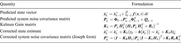
Table 3 shows the Kalman filter algorithm (Groves, Reference Groves2013), where  ${\hat{\bi x}}_k^ - $ is the a priori state estimate at a time step k, $ {\hat{\bi x}}_{k - 1}^ + $ is the a posteriori state estimate at a time step k − 1, ${\bf \Phi} _{k - 1} $ is the state transition matrix at a time step k − 1, ${\bi P}_k^ - $ is the a priori estimate error covariance at a time step k, ${\bi P}_{k - 1}^ + $ is the a posteriori estimate error covariance at a time step k − 1, Qk−1 is the discrete process noise covariance a time step k − 1, Rk is the discrete measurement noise covariance at a time step k, Hk is the measurement matrix at a time step k, Kk is the Kalman gain at a time step k, zk is the measurement vector at a time step k, $\delta {\bi z}_k^ - $ is the innovation measurement vector at a time step k and I is a unit matrix.
Table 3. Extended Kalman Filter (EKF) algorithm for navigation.
4.1. State vector and measurements vector
The state vector is composed of eight elements; it includes the position and velocity components of the spacecraft, and the receiver's clock offset b and clock drift  $\dot b$.
 $${\bi x} = \left[ {\matrix{ x & y & {\matrix{ z & {\matrix{ {\matrix{ b & u & v \cr}} & {\matrix{ w & {\dot b} \cr}}}}}}}} \right]^T $$
The measurement vector is
 $${\bi z} = \left[ {\matrix{ {{\bi \rho} _{GPS}} \cr {{\dot {\bi \rho}} _{GPS}} \cr}} \right] $$
where ρGPS are the pseudoranges of the available GPS satellites and  ${\dot {\bi \rho}} _{GPS}$ are the pseudorange rates of the available GPS satellites.
4.2. Spacecraft dynamics model
Different accelerations are included in the model by three different configurations:
1. below 9600 km from the centre of the Earth, spherical harmonics of Earth gravitational potential up to 6th degree and 6th order;
2. in between 9600 km and 50 000 km, spherical harmonics up to 2nd degree and 2nd order, the Solar Radiation Pressure (SRP) and the gravitational perturbations due to the Sun and the Moon;
3. above 50 000 km, 1st order Earth gravity, SRP and lunar and solar third body perturbations.
Although at low altitude the atmospheric drag has a significant effect on a satellite's orbit, it is not modelled since the benefit in the navigation solution's accuracy obtainable by including the drag in the process is not considered worth the computational cost required and in addition, the GNSS stand-alone performance is very accurate in LEO.
The computation of the Earth gravitational potential and the acceleration of the spacecraft due to a second and third perturbing mass (which in our case are the Sun and the Moon) have been modelled according to Montenbruk and Gill (Reference Montenbruck and Gill2000) while the effect of the SRP according to Battin (Reference Battin1999). However, more details can be found in Basile (Reference Basile2014).
Figure 7 shows the 3D position error over time if the trajectory is estimated by only integrating the dynamics equations, thus as pure orbital propagation. A typical drift affects the propagation reaching almost 300 km of error at the end of the MTO. It is important to note that both the GNSS and the orbital propagator systems if used individually provide a very coarse accuracy at the end of the MTO (see Figures 4 and 7). However, since the position estimation of both systems is characterised by a different error distribution, their fusion can result in a significant improvement of the individual accuracy (as will be shown in the results of Section 5); in fact the GNSS measurements prevent the orbital propagation solution drifting, while the orbital propagation smooths the GNSS solution and bridges signal outages.
Figure 7. Orbital propagator 3D position error over time for the full MTO.
4.3. Observation functions
The GNSS receiver provides n measurements of pseudorange ρ and pseudo-range rate  $\dot \rho $ from n different transmitting satellites. These measurements are predicted by the following observation functions of the state vector (Kaplan and Hegarty, Reference Kaplan and Hegarty2006):
 $$\rho ^ - = \sqrt {\left( {x_{sat} - x^ -} \right)^2 + \left( {y_{sat} - y^ -} \right)^2 + \left( {z_{sat} - z^ -} \right)^2} + b^ - $$
 $$\dot \rho ^ - = \left( {{\bi v}_{{\bi sat}} - {\bi v}^ -} \right) \cdot {\bi a}^ - + \dot b^ - $$
 In Equation (11),  $\left[ {\matrix{ {x_{sat}} & {y_{sat}} & {z_{sat}} \cr}} \right]^T $ denotes the position's vector of the GNSS satellite that is transmitting the signal, $\left[ {\matrix{ {x^ - } & {y^ - } & {z^ - } \cr}} \right]^T $ is the predicted user's position vector, and b − is the predicted receiver's clock offset. In Equation (12), vsat and v− are, respectively, the velocity vector of the transmitting GNSS satellite and the velocity vector of the spacecraft, $\dot b^ - $ represents the predicted clock's drift, and a− is the predicted line-of-sight (LOS) unit vector from the user to the GNSS satellite.
The predicted observation vector z− consists of 2n elements:
 $${\bi z}^ - = {\bi h}\left( {{\bi x}^ -} \right) = \left[ {\matrix{ {\rho _1 ^ -} & {\rho _2 ^ -} & {\matrix{ \cdots & {\rho _n ^ -} & {\matrix{ {\dot \rho _1 ^ -} & {\dot \rho _2 ^ -} & {\matrix{ \cdots & {\dot \rho _n ^ -} \cr}} \cr}} \cr}} \cr}} \right]^T $$
4.4. State transition matrix computation
The state transition matrix Φ is required to compute the predicted system noise covariance matrix. The transition matrix can be expressed as:
 $${\bf \Phi} _{k - 1} = exp\left( {{\bi F}_{k - 1} \tau _s} \right) \cong \left( {{\bi I} + {\bi F}_{k - 1} \tau _s} \right), $$
where τ s = t k − t k−1 is the propagation interval, while:
 $${\bi F}_{k - 1} = \left. {\displaystyle{{\partial {\bi f}\left( {\bi x} \right)} \over {\partial {\bi x}}}} \right \vert _{{\bi x} = {\hat{\bi x}}_{k - 1}^ +} $$
 As shown in Equation (14), Φ is a function of the system matrix F, which is linearized about the state vector estimate (see Equation (15)). To compute the system matrix F linearized about the state vector estimate  ${\hat{\bi x}}^ + $ the complex-step derivative approximation is adopted. This method has been investigated in many works (e.g. Anderson et al., Reference Anderson, Newman and Nielsen2001; Lai and Crassidis Reference Lai and Crassidis2006; Martins et al., Reference Martins, Sturdza and Alonso2003).
4.5. Observation matrix
The observation matrix H at a time step k is defined as the Jacobian of the observations defined in Equations (11) and (12):
 $${\bi H}_k = \left. {\displaystyle{{\partial {\bi h}\left( {\bi x} \right)} \over {\partial {\bi x}}}} \right \vert _{{\bi x} = {\hat{\bi x}}_k^ -} = \left. {\displaystyle{{\partial {\bi z}\left( {\bi x} \right)} \over {\partial {\bi x}}}} \right \vert _{{\bi x} = {\hat{\bi x}}_k^ -}. $$
Thus, it corresponds to the following 2n × 8 matrix :
 $${\bi H}_k = \left[ {\matrix{ {ax_1} & {ay_1} & {az_1} & 1 & 0 & 0 & 0 & 0 \cr {ax_2} & {ay_2} & {az_2} & 1 & 0 & 0 & 0 & 0 \cr \vdots & \vdots & \vdots & \vdots & \vdots & \vdots & \vdots & \vdots \cr {ax_n} & {ay_n} & {az_n} & 1 & 0 & 0 & 0 & 0 \cr 0 & 0 & 0 & 0 & {ax_1} & {ay_1} & {az_1} & 1 \cr 0 & 0 & 0 & 0 & {ax_2} & {ay_2} & {az_2} & 1 \cr \vdots & \vdots & \vdots & \vdots & \vdots & \vdots & \vdots & \vdots \cr 0 & 0 & 0 & 0 & {ax_n} & {ay_n} & {az_n} & 1 \cr}} \right]$$
where  $\left[ {\matrix{ {a_{xj}} & {a_{yj}} & {a_{zj}} \cr}} \right]^T $ represents the LOS vector between the receiver and the jth satellite at a time step k. Note that the dependence of the pseudorange rate on the position is not null but it can be considered negligible; in fact for an Earth user a 1 m position error has an impact on the psudorange rate of only $\sim 5 \times 10^{ - 5} {\rm m\; s}^{ - 1} $ (Groves, Reference Groves2013) and then even less during most of the MTO.
4.6. Adaptivity of the filter
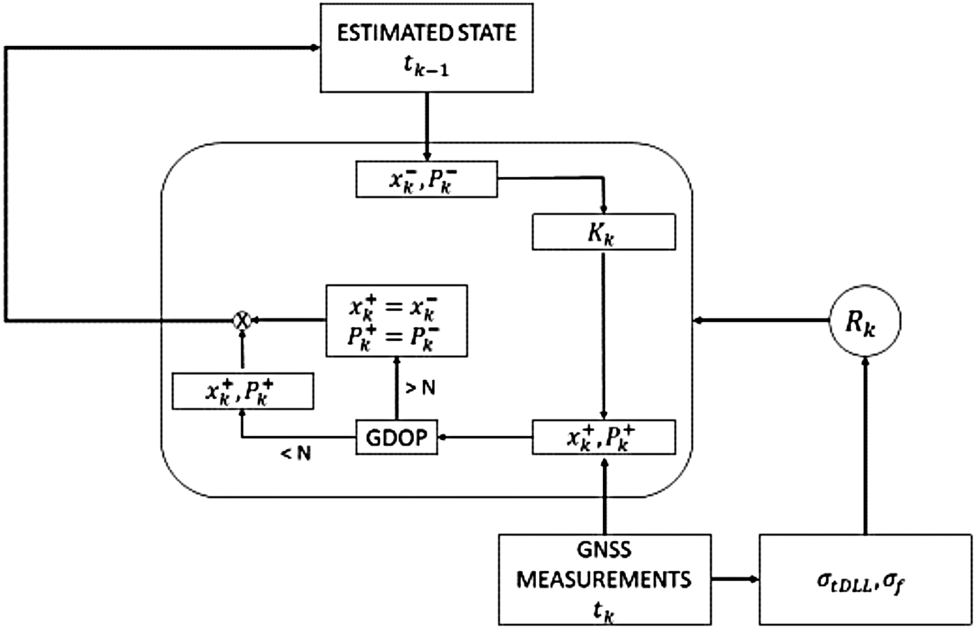
The accuracy of the observations strongly worsens with the altitude along the MTO, as shown in Section 3.1.1. Therefore the covariance matrix Rk of the measurements is tuned adaptively as a function of the GNSS measurements error. The adaptive strategy adopted is illustrated in Figure 8. The code tracking thermal noise σ tDLL and the Doppler tracking jitter σ f (that affect respectively pseudoranges and pseudorange rates) are computed by means of the C/N 0, by using Equations (5) and (6), respectively. Once Rk is computed, as a function of the current σ UERE, the EKF provides the navigation solution by fusing the prediction of the dynamics and the GNSS measurements. As stated previously, the GDOP can be very high, resulting in very large position error peaks. In order to remove such large error peaks, the orbital filter makes a check of the GDOP computed by means of the estimated state and, if it exceeds a threshold N (a value of 1500 has been set after tuning), the estimation will only rely on the orbital propagation. Corresponding to GDOP peaks higher than the threshold, the measurements are considered not reliable enough and the orbital propagator is used to bridge the consequent outage. This is not statistically optimal, but for the very short time intervals of the GDOP peaks, it provides higher accuracy. While Rk is a function of σ UERE, Qk is constant. The following results have been obtaining setting Rk and Qk as reported in Table 4.
Figure 8. Adaptive strategy.
Table 4. Adopted measurement and process covariance matrices. The symbols  ${\bi \sigma} _{{\bi \rho}_{\bi i}}$ and ${\bi \sigma} _{{\dot {\bi \rho}}_{\bi i}}$ represent respectively the root sum square of the different range error contributions (defined as ${\bi \sigma} _{{\bi UERE}}$) and the Doppler tracking jitter defined in Equation (6).

4.7. Frequency aiding for the GNSS receiver
A precise estimation of Doppler shifts and Doppler rates that affect the carrier frequency can provide a precious aiding to the signal processing engine as described in Capuano et al. (Reference Capuano, Botteron, Wang, Tian, Leclère and Farine2014; Reference Capuano, Botteron, Leclere, Tian, Yanguang and Farine2015) and Silva et al. (Reference Silva, Lopes, Peres, Silva, Ospina, Cichocki, Dovis, Musumeci, Serant, Calmettes, Pessina and Perelló2013). Expected Doppler shifts Δf expected can be computed from the estimated range rate  $\dot r_{estimated} $ by means of the more accurate filtered navigation solution and of the GNSS satellites ephemeris as
 $${\rm \Delta }{\,f_{expected}} = - \displaystyle{{{\,f_T}} \over c} \cdot {{\dot r}_{estimated}} $$
where f T is the transmitted frequency (e.g. 1575·42 MHz for GPS L1) and c is the speed of light.
In addition, expected Doppler rate  ${{\dot{\rm \Delta}} f}_{expected} $ can be computed as follows:
 $${\dot{\rm \Delta}} {\,f} _{expected} = \displaystyle{{{\rm \Delta }{\,f_{expected}}\left( {{t_{k + 1}}} \right) - {\rm \Delta }{\,f_{expected}}\left( {{t_k}} \right)} \over {{t_{k + 1}} - {t_k}}}. $$
5. RESULTS
5.1. GPS L1 C/A-based orbital filter performance
Figure 9 highlights the accuracy achievable by the implemented GPS L1 C/A-based orbital filter, in terms of 3D position error. The maximum error is about 260 m, more than two orders of magnitude less than the maximum error obtained with the stand-alone GPS receiver. For the last 5 hours and 45 minutes of orbit (i.e. the last portion where the error does not drift significantly, which starts approximately at 376200 km altitude), the standard deviation is equal to 80·5 m (1σ). Similar results have been obtained in (Silva et al., Reference Silva, Lopes, Peres, Silva, Ospina, Cichocki, Dovis, Musumeci, Serant, Calmettes, Pessina and Perelló2013), for a MTO with a minimum C/N0 = 15 dB-Hz and with a minimum C/N0 = 10 dB-Hz.
Figure 9. 3D normalised position error obtained with the GPS-based orbital filter.
Figure 10 displays the 3D velocity error of the GPS L1 C/A orbital filtered solution. In the last 5 hours and 45 minutes of the MTO, the standard deviation is about 9·51 cm/s (1σ).
Figure 10. 3D normalised velocity error obtained with the GPS-based orbital filter.
By considering for example one of the 12 channel outputs of Spirent (the first one) for the last 5 hours and 45 minutes of orbit, the GPS L1 C/A orbital filtered solution can predict the Doppler shift and Doppler rate with an error of about 0·061 Hz and 0·039 Hz/s standard deviation (1σ) respectively, as illustrated for the whole trajectory in Figures 11 and 12.
Figure 11. Doppler shift estimation error for the first channel output of Spirent: GPS-based orbital filter.
Figure 12. Doppler rate estimation error for the first channel output of Spirent: GPS-based orbital filter.
5.2. Use of GPS-Galileo combined constellation
Figure 13 illustrates the improvement achievable in availability when using a GPS-Galileo combined constellation and Figure 14 the consequent reduction of the GDOP as compared to using GPS only. As a combined result of better availability and smaller GDOP, the performance in the position estimation are improved too, as shown in Figure 15: during the last 5 hours and 45 minutes of the simulation, the standard deviation of the 3D position error is approximately 9 m (1σ), one order of magnitude less than that obtained in the single constellation case (see Figure 9).
Figure 13. GNSS availability for a single GPS constellation and for a GPS-Galileo combined constellation, for a sensitivity of −159 dBm.
Figure 14. GDOP for a single GPS constellation and for a GPS-Galileo combined constellation, for a sensitivity of −159 dBm.
Figure 15. 3D normalised position error obtained with the GPS-Galileo-based orbital filter.
Figure 16 shows the velocity estimate accuracy, in terms of 3D velocity error, improved too. In the last 5 hours and 45 minutes of trajectory, we obtained about 3·5 cm/s (1σ), much better than the GPS only-based orbital filter.
Figure 16. 3D normalised velocity error obtained with the GPS-Galileo-based orbital filter.
The improvements in the navigation solution lead to a better estimation of the Doppler shift and Doppler rate as well, as shown in Figures 17 and 18, with an error of 0·041 Hz and 0·021 Hz/s (1σ) respectively during the last 5 hours and 45 minutes of considered trajectory.
Figure 17. Doppler shift estimation error for the first channel output of Spirent: GPS + Galileo-based orbital filter.
Figure 18. Doppler rate estimation error for the first channel output of Spirent: GPS + Galileo-based orbital filter.
Adding GLONASS and BeiDou (as future GNSS receivers probably will do) should further improve the GDOP.
6. CONCLUSIONS
Several studies have proved the feasibility of GNSS as a navigation system for high Earth orbits and in particular for Moon missions. Although the very weak GNSS signals at the Moon's altitude can be processed with modern high sensitivity GNSS receivers, the accuracy of a standalone GNSS navigation solution would be much lower than that typically required for a Moon mission. In this paper we have investigated the use of an orbital filter, specifically designed for a MTO, which fuses GNSS observations of pseudorange and pseudorange rate with an orbital forces model through an adaptive EKF. A reference trajectory and a realistic operational scenario have been defined to reproduce a direct MTO of a Moon mission. The positioning error achievable by using a least square estimator of the available GPS observations has been simulated to quantify what would be the accuracy of a non-filtered standalone GPS L1 C/A receiver during the whole trajectory. As expected, once the receiver is flying above the GPS constellation, the positioning error increases with the altitude because of a decreasing accuracy of the GNSS measurements. This is due to weaker signals and a worsening of the relative geometry between receiver and transmitters (higher GDOP). Without any kind of filtering tens of km error with peaks higher than 50 km have been observed in simulation at Moon altitude, assuming a GPS L1 C/A receiver capable of tracking signals down to −159 dBm.
The implementation of our orbital filter has been described, highlighting the importance of its adaptive architecture that takes into account the decreasing accuracy of the GNSS observations when the receiver is orbiting above the GNSS constellation on the route to the Moon. Simulation results have shown a significant improvement of the positioning accuracy when using the orbital filter. The peaks of the error have been reduced to about 260 m by filtering the same GPS L1 C/A observations used for the least square estimation. Accuracies of tens of cm/s have been obtained for the velocity estimation. Position and velocity estimation have also been used to estimate Doppler shift and Doppler rate; very useful to aid the signal processing module of the GNSS receiver. The Doppler shift and Doppler rate estimation errors have a standard deviation of 0·06 Hz and of 0·04 Hz/s at Moon altitude, respectively. Finally we have investigated the improvements achievable when using observations from a GPS-Galileo combined constellation. Significant further improvements are attained in positioning, velocity, Doppler shift and Doppler rate estimation when using the two constellations concurrently. However, without cross-validation using real input data, the results obtained by using the Kalman filter have to be treated cautiously. In order to validate the system experimentally, in future works the orbital filter effectiveness will be tested using measurements provided by our GPS L1 C/A space-borne WeakHEO receiver, under development, specifically designed for lunar missions.