


1. Introduction
When a shock wave strikes a geometrically well-defined density inhomogeneity, the processes of both refraction and reflection generally take place simultaneously. As a canonical problem in compressible multi-hydrodynamics, shock refraction at an interface has attracted much attention in the past decades. A theoretical description of the regular refraction phenomenon has been formulated independently by Taub (Reference Taub1947) and Polachek & Seeger (Reference Polachek and Seeger1951). These studies, however, are generally inadequate to describe a complex process such as an irregular refraction phenomenon. Shock tube experiments were then performed by Jahn (Reference Jahn1956) to study the refraction of planar shock waves at air/
 $\text{CH}_{4}$
and air/
$\text{CH}_{4}$
and air/
 $\text{CO}_{2}$
interfaces, respectively, and both regular and irregular refraction phenomena were observed for each case. Subsequently, extensive experimental, numerical and theoretical examinations of a shock refraction at either a slow/fast or a fast/slow interface were made (Henderson Reference Henderson1966; Abd-el Fattah, Henderson & Lozzi Reference Abd-el Fattah, Henderson and Lozzi1976; Abd-el Fattah & Henderson Reference Abd-el Fattah and Henderson1978a
,Reference Abd-el Fattah and Henderson
b
; Henderson, Colella & Puckett Reference Henderson, Colella and Puckett1991; Henderson & Puckett Reference Henderson and Puckett2014) for more gas combinations such as
$\text{CO}_{2}$
interfaces, respectively, and both regular and irregular refraction phenomena were observed for each case. Subsequently, extensive experimental, numerical and theoretical examinations of a shock refraction at either a slow/fast or a fast/slow interface were made (Henderson Reference Henderson1966; Abd-el Fattah, Henderson & Lozzi Reference Abd-el Fattah, Henderson and Lozzi1976; Abd-el Fattah & Henderson Reference Abd-el Fattah and Henderson1978a
,Reference Abd-el Fattah and Henderson
b
; Henderson, Colella & Puckett Reference Henderson, Colella and Puckett1991; Henderson & Puckett Reference Henderson and Puckett2014) for more gas combinations such as
 $\text{CO}_{2}$
/helium and air/
$\text{CO}_{2}$
/helium and air/
 $\text{SF}_{6}$
. It was found that the type of shock refraction is closely related to the shock strength, the gas combination and the incident angle. Shock refraction phenomena at a slow/fast interface are more complicated than those at a fast/slow one (Abd-el Fattah & Henderson Reference Abd-el Fattah and Henderson1978a
,Reference Abd-el Fattah and Henderson
b
). For the slow/fast case, the appearances of bound and free precursor shocks are the most remarkable features in the irregular refraction system. For the fast/slow case, the main feature that distinguishes the regular and irregular refraction systems is the formation of the Mach stem.
$\text{SF}_{6}$
. It was found that the type of shock refraction is closely related to the shock strength, the gas combination and the incident angle. Shock refraction phenomena at a slow/fast interface are more complicated than those at a fast/slow one (Abd-el Fattah & Henderson Reference Abd-el Fattah and Henderson1978a
,Reference Abd-el Fattah and Henderson
b
). For the slow/fast case, the appearances of bound and free precursor shocks are the most remarkable features in the irregular refraction system. For the fast/slow case, the main feature that distinguishes the regular and irregular refraction systems is the formation of the Mach stem.
In the experiments described above, a misalignment is often preserved between the shock front and the interface. Therefore, accompanied by the shock refraction, baroclinic vorticity will be produced and deposited on the interface due to the misalignment between the pressure and density gradients. Baroclinic vorticity will induce the deformation of the interface and enhance the mixing between the fluids. This is a problem of fundamental interest, called Richtmyer–Meshkov instability (RMI) because of the pioneering contributions made by Richtmyer (Reference Richtmyer1960) and Meshkov (Reference Meshkov1969). In the previous studies of shock refraction stated above, however, due to the small time scale (only the time of the shock passing through the interface) and different concerns, investigations were seldom focused on the interface development. Ever since the RMI problem was proposed, it has become increasingly attractive owing to the academic significance of the mechanism of turbulent mixing formation and important applications in many fields such as inertial confinement fusion (Lindl et al. Reference Lindl, Landen, Edwards, Moses and Team2014) and supernova explosions (Arnett et al. Reference Arnett, Bahcall, Kirshner and Woosley1989).
It is crucial to generate a well-controlled initial interface for investigating the shock refraction phenomena and shock–interface interactions. In experiments studying shock refraction, a planar interface with different inclinations was generally formed. It was found that the material and thickness of the interface, as well as the concentration of the gases at both sides of the interface, will affect the wave patterns. Besides an inclined interface, many other shapes of interfaces have been considered in RMI experiments because the initial shape has significant effects on the shock dynamics phenomenon and perturbation development. In earlier experiments, nitrocellulose film was adopted to form a two-dimensional (2D) single-mode interface (Meshkov Reference Meshkov1969; Vetter & Sturtevant Reference Vetter and Sturtevant1995; Sadot et al. Reference Sadot, Erez, Alon, Oron, Levin, Erez, Ben-Dor and Shvarts1998) where a wire mesh was used to support the membrane. However, the fragments of the membrane after the shock impact have an adverse effect on the flow field during the early stage. In order to avoid the influence of the membrane, the membraneless 2D interface was generated by retracting a plate between two different gases (Brouillette & Sturtevant Reference Brouillette and Sturtevant1993; Bonazza & Sturtevant Reference Bonazza and Sturtevant1996). The thickness of the interface created by this method is comparable to or even exceeds the perturbation wavelength, which significantly slows the growth of instability. Subsequently, a novel technique was created by Jones & Jacobs (Reference Jones and Jacobs1997) and later adopted by others (Long et al. Reference Long, Krivets, Greenough and Jacobs2009; Jacobs et al. Reference Jacobs, Krivets, Tsiklashvili and Likhachev2013) in a vertical shock tube in which the interface was generated by flowing light or heavy gas from opposite sides of the shock tube driven section and an initial 2D disturbance was realized by oscillating the shock tube at a prescribed frequency in the horizontal direction. In order to precisely control the initial 2D perturbation, Mariani et al. (Reference Mariani, Vanderboomgaerde, Jourdan, Souffland and Houas2008) used stereolithography to design the membrane supports which initially materialized the gaseous interface. Three-dimensional (3D) RMI was also studied by Luo, Wang & Si (Reference Luo, Wang and Si2013), who used the soap film technique to create a discontinuous gaseous interface with minimum surface feature and examined the 3D effect on the RMI. In addition to the single-mode interface, spherical and cylindrical interfaces were also extensively investigated as the most classical categories of the RMI. The soap film technique was adopted in most experiments to generate the spherical gas interface with or without support (Haas & Sturtevant Reference Haas and Sturtevant1987; Hosseini & Takayama Reference Hosseini and Takayama2005; Ranjan et al. Reference Ranjan, Anderson, Oakley and Bonazza2005, Reference Ranjan, Niederhaus, Oakley, Anderson, Bonazza and Greenough2008; Layes, Jourdan & Houas Reference Layes, Jourdan and Houas2009; Zhai et al. Reference Zhai, Si, Luo and Yang2011; Haehn et al. Reference Haehn, Ranjan, Weber, Oakley, Rothamer and Bonazza2012; Si et al. Reference Si, Zhai, Luo and Yang2012) to study the shock–bubble interaction. The shock phenomena, such as shock refraction, diffraction and focusing, were also discussed, using acoustic theory (Haas & Sturtevant Reference Haas and Sturtevant1987) and high-speed diagnostic technique (Zhai et al. Reference Zhai, Si, Luo and Yang2011), for example. For cylindrical interfaces, a nitrocellulose membrane was used by Haas & Sturtevant (Reference Haas and Sturtevant1987) to confine the test gas within the cylindrical volume. Later, the jet technique, developed by Jacobs (Reference Jacobs1992), became a primary way of forming a circular gas cylinder (Jacobs Reference Jacobs1993; Tomkins et al. Reference Tomkins, Kumar, Orlicz and Prestridge2008; Zhai et al. Reference Zhai, Zhang, Si and Luo2014b ), an elliptical gas cylinder (Zou et al. Reference Zou, Liu, Tan, Huang and Luo2010), two gas cylinders (Tomkins et al. Reference Tomkins, Prestridge, Rightley, Marr-Lyon, Vorobieff and Benjamin2003), three gas cylinders (Kumar et al. Reference Kumar, Orlicz, Tomkins, Goodenough, Prestridge, Vorobieff and Benjamin2005) and a gas curtain (Orlicz et al. Reference Orlicz, Balakumar, Tomkins and Prestridge2009; Balakumar et al. Reference Balakumar, Orlicz, Ristorcelli, Balasubramanian, Prestridge and Tomkins2012; Balasubramanian et al. Reference Balasubramanian, Orlicz, Prestridge and Balakumar2012; Tomkins et al. Reference Tomkins, Balakumar, Orlicz, Prestridge and Ristorcelli2013).
The interface shapes in the RMI study were mainly confined to planar, spherical, cylindrical or single-mode cases and only a few works have dealt with other types. Mikaelian (Reference Mikaelian2005) theoretically and numerically studied the RMI on the initial interface with a discontinuous change in its first derivative. Fan et al. (Reference Fan, Zhai, Si, Luo, Zou and Tan2012) numerically investigated the interaction of a planar shock with several kinds of polygon, in which the wave patterns, the interface evolution modes, and the circulation deposition were analysed and compared. Experimentally, Bakhrakh et al. (Reference Bakhrakh, Klopov, Meshkov, Tolshmyakov and Yanilkin1995) created a 2D disturbance with a complex shape (i.e. ‘saw’ and ‘step’) where a thin organic film was placed at joints between the units which were filled with gases of various densities. Furthermore, the double-bump, trapezoid and chevron, and inverse chevron profiled interfaces were produced by Smith et al. (Reference Smith, Holder, Barton, Morris and Youngs2001), Holder et al. (Reference Holder, Smith, Barton and Youngs2003) and Holder & Barton (Reference Holder and Barton2004), respectively. Bates, Nikiforakis & Holder (Reference Bates, Nikiforakis and Holder2007) considered a shock passing through a semi-rectangular
 $\text{SF}_{6}$
block which was produced by the microfilm membrane supported by a fine wire mesh. Recent work by Wang, Si & Luo (Reference Wang, Si and Luo2013) and Zhai et al. (Reference Zhai, Wang, Si and Luo2014a
) in our group used thin pins to restrict soap film to form various polygonal inhomogeneities, and the developments of polygonal interfaces induced by a shock wave were investigated. Similar to spherical or cylindrical interfaces, polygonal interfaces can also be used as the building block for RMI study. Furthermore, a polygonal interface provides good conditions for the study of shock refraction because of the unique feature that the incident angle is constant along the edge, which provides an important controlling parameter for baroclinic vorticity.
$\text{SF}_{6}$
block which was produced by the microfilm membrane supported by a fine wire mesh. Recent work by Wang, Si & Luo (Reference Wang, Si and Luo2013) and Zhai et al. (Reference Zhai, Wang, Si and Luo2014a
) in our group used thin pins to restrict soap film to form various polygonal inhomogeneities, and the developments of polygonal interfaces induced by a shock wave were investigated. Similar to spherical or cylindrical interfaces, polygonal interfaces can also be used as the building block for RMI study. Furthermore, a polygonal interface provides good conditions for the study of shock refraction because of the unique feature that the incident angle is constant along the edge, which provides an important controlling parameter for baroclinic vorticity.
Note that in our previous paper on heavy polygons (Wang et al.
Reference Wang, Si and Luo2013) the emphasis was on the validation of the method of interface formation, and only few analyses on the interface scales were performed. In our previous work (Zhai et al.
Reference Zhai, Wang, Si and Luo2014a
), three types of light polygonal interface (i.e. nitrogen polygon surrounded by
 $\text{SF}_{6}$
) were considered, including a square, a triangle and a diamond, and the wave patterns were checked. It was found that the irregular wave pattern of free precursor refraction (FPR) is transformed from free precursor von Neumann refraction (FNR), which provides the experimental evidence for the earlier work (Jahn Reference Jahn1956; Abd-el Fattah & Henderson Reference Abd-el Fattah and Henderson1978b
). In light inhomogeneities, for the square, only one vortex pair is formed from the upstream corners, and for the triangle and the diamond, the remarkable features are the generation of the inward jet from the upstream cusp and the penetration of the jet through the downstream boundary. The present work is a follow-up consideration of the interaction of a shock with a polygonal light interface, with an
$\text{SF}_{6}$
) were considered, including a square, a triangle and a diamond, and the wave patterns were checked. It was found that the irregular wave pattern of free precursor refraction (FPR) is transformed from free precursor von Neumann refraction (FNR), which provides the experimental evidence for the earlier work (Jahn Reference Jahn1956; Abd-el Fattah & Henderson Reference Abd-el Fattah and Henderson1978b
). In light inhomogeneities, for the square, only one vortex pair is formed from the upstream corners, and for the triangle and the diamond, the remarkable features are the generation of the inward jet from the upstream cusp and the penetration of the jet through the downstream boundary. The present work is a follow-up consideration of the interaction of a shock with a polygonal light interface, with an
 $\text{SF}_{6}$
polygon surrounded by air (heavy inhomogeneity) under consideration. The wave patterns of a shock refraction at a fast/slow interface are completely different from those at a slow/fast one, and the evolution mode of a heavy gas interface accelerated by a shock wave is also distinguished from that of a light gas interface. It is therefore quite significant to check the wave patterns of a shock refraction at a fast/slow polygonal interface and to explore the effect of the initial interface shape on the RMI of heavy polygonal inhomogeneity and other research areas, which motivates this study.
$\text{SF}_{6}$
polygon surrounded by air (heavy inhomogeneity) under consideration. The wave patterns of a shock refraction at a fast/slow interface are completely different from those at a slow/fast one, and the evolution mode of a heavy gas interface accelerated by a shock wave is also distinguished from that of a light gas interface. It is therefore quite significant to check the wave patterns of a shock refraction at a fast/slow polygonal interface and to explore the effect of the initial interface shape on the RMI of heavy polygonal inhomogeneity and other research areas, which motivates this study.
2. Experimental methods
In experiments, the same soap film technique as in our previous work (Wang et al. Reference Wang, Si and Luo2013; Zhai et al. Reference Zhai, Wang, Si and Luo2014a ) is adopted to form six polygonal inhomogeneities including a square, two types of rectangle, two types of triangle, and a diamond. To avoid the pressure singularity caused by surface tension, thin pins are introduced to connect the adjacent sides of the polygonal soap film at the vertexes. Specifically, the thin pins (0.25 mm in diameter) at the corner of the polygon are first fixed between two parallel Plexiglas plates (3 mm in thickness) in the test section. Then, by blowing the soap bubble into the test section, the soap film will be perpendicular to the Plexiglas plates at contact due to surface tension. When the soap film connects all pins, blowing of gas stops. At this time, the volume formed is over-expanded due to the over-pressure inside and has a circular cross-section. Then the pressure inside the soap bubble is decreased by pumping out the gas until the soap films connecting the pins become flat (the real-time image of the formed interface is monitored by the diagnostic system reported below). Now an almost ideal 2D polygonal gas inhomogeneity is formed. Figure 1 presents the schematic structures of six interface shapes studied in this work and shows three typical examples of the vertex formation. For convenience, according to the flow direction from left to right in figure 1, two types of rectangle, i.e. streamwise-rectangle and transverse-rectangle, and two types of triangle, i.e. forward-triangle and backward-triangle, are identified, respectively. The polygonal interface produced differs from the ideal one due to the existence of thin pins and fine chamfers at the vertexes. The effects caused by these two differences on the shock propagation and on the interface evolution were evaluated by numerical simulations and shock tube experiments, and were found to be limited, as presented in our previous work (Wang et al. Reference Wang, Si and Luo2013).

Figure 1. Schematic diagrams of the interface shapes studied in this work. The incident shock travels from left to right.
The experiments are performed in a horizontal shock tube which consists of a 1.7 m driver section, a 2.0 m driven section and a 0.5 m test section with a rectangular cross-sectional area of
 $140~\text{mm}\times 20~\text{mm}$
. The initial interface centre is 0.3 m distant from the end of the test section, and an end section with a length of 0.7 m is connected to the test section to avoid the influence of the reflected shock from the end wall. The height of the test section is small (20 mm) to minimize any gravity effect on the test gas and to decrease any 3D effect on the interface. The Mach number (
$140~\text{mm}\times 20~\text{mm}$
. The initial interface centre is 0.3 m distant from the end of the test section, and an end section with a length of 0.7 m is connected to the test section to avoid the influence of the reflected shock from the end wall. The height of the test section is small (20 mm) to minimize any gravity effect on the test gas and to decrease any 3D effect on the interface. The Mach number (
 $M$
) of the initial shock wave measured by two piezoelectric pressure transducers mounted in the driven section is
$M$
) of the initial shock wave measured by two piezoelectric pressure transducers mounted in the driven section is
 $1.18\pm 0.01$
. In our experiments, a plastic diaphragm with a thickness of 0.026 mm is first placed between the driver and driven sections, and then the shock wave is generated by filling the driver section with high pressure gas until the diaphragm is burst. Figure 2 shows the schlieren system and the initial gas interface setup in the test section of the shock tube. The schlieren system includes a light source, a blade, two lenses, two concave mirrors and a high-speed video camera. In order to maintain the initial interface shape, the visualizing windows are arranged vertically by placing two plane mirrors (200 mm in diameter) on both sides of the test section to change the path of the parallel light. The flow is illuminated by a DC regulated light source (DCR III, SCHOTT North America, Inc.) and captured by a high-speed video camera (FASTCAM SA5, Photron Limited). In the present study, the frame rate of the high-speed video camera is up to 42 000 f.p.s., the shutter speed of the camera is
$1.18\pm 0.01$
. In our experiments, a plastic diaphragm with a thickness of 0.026 mm is first placed between the driver and driven sections, and then the shock wave is generated by filling the driver section with high pressure gas until the diaphragm is burst. Figure 2 shows the schlieren system and the initial gas interface setup in the test section of the shock tube. The schlieren system includes a light source, a blade, two lenses, two concave mirrors and a high-speed video camera. In order to maintain the initial interface shape, the visualizing windows are arranged vertically by placing two plane mirrors (200 mm in diameter) on both sides of the test section to change the path of the parallel light. The flow is illuminated by a DC regulated light source (DCR III, SCHOTT North America, Inc.) and captured by a high-speed video camera (FASTCAM SA5, Photron Limited). In the present study, the frame rate of the high-speed video camera is up to 42 000 f.p.s., the shutter speed of the camera is
 $1/521\,000~\text{s}$
and the pixel resolution is
$1/521\,000~\text{s}$
and the pixel resolution is
 $0.39~\text{mm}~\text{pixel}^{-1}$
.
$0.39~\text{mm}~\text{pixel}^{-1}$
.

Figure 2. Schematic diagram of the schlieren system.
3. Interface morphology
The experimental schlieren images of a planar shock interacting with six types of polygonal interface separating
 $\text{SF}_{6}$
from air (fast/slow/fast) are presented in figures 3–8 (also see supplementary movies 1–6 available at http://dx.doi.org/10.1017/jfm.2015.257). Note that during the pumping process the soap film will leave some remnants on the Plexiglas plates, as can be seen in the experimental schlieren images. For all cases, the moment when the shock contacts the leftmost part of the interface is defined as the initial time (i.e.
$\text{SF}_{6}$
from air (fast/slow/fast) are presented in figures 3–8 (also see supplementary movies 1–6 available at http://dx.doi.org/10.1017/jfm.2015.257). Note that during the pumping process the soap film will leave some remnants on the Plexiglas plates, as can be seen in the experimental schlieren images. For all cases, the moment when the shock contacts the leftmost part of the interface is defined as the initial time (i.e.
 $t=0$
).
$t=0$
).

Figure 3. Experimental schlieren images of the shocked
 $\text{SF}_{6}$
square inhomogeneity.
$\text{SF}_{6}$
square inhomogeneity.
 $M=1.17$
. IS, incident shock; TS, transmitted shock; RS, refracted shock; TP, triple point; MS, Mach stem; DS, diffracted shock; S1 and S2 are the products of the interaction between the TS and RS. UVR, upstream vortex pair; DVR, downstream vortex pair;
$M=1.17$
. IS, incident shock; TS, transmitted shock; RS, refracted shock; TP, triple point; MS, Mach stem; DS, diffracted shock; S1 and S2 are the products of the interaction between the TS and RS. UVR, upstream vortex pair; DVR, downstream vortex pair;
 $Lv$
, vortex spacing. The numbers indicate the time after the shock impact and the unit is
$Lv$
, vortex spacing. The numbers indicate the time after the shock impact and the unit is
 ${\rm\mu}\text{s}$
.
${\rm\mu}\text{s}$
.

Figure 4. Experimental schlieren images of the shocked
 $\text{SF}_{6}$
streamwise-rectangle inhomogeneity.
$\text{SF}_{6}$
streamwise-rectangle inhomogeneity.
 $M=1.18$
. SDVR, second downstream vortex pair. Other symbols and the description of the wave patterns are the same as those in figure 3.
$M=1.18$
. SDVR, second downstream vortex pair. Other symbols and the description of the wave patterns are the same as those in figure 3.

Figure 5. Experimental schlieren images of the shocked
 $\text{SF}_{6}$
transverse-rectangle inhomogeneity.
$\text{SF}_{6}$
transverse-rectangle inhomogeneity.
 $M=1.19$
. The symbols and the description of the wave patterns are the same as those in figure 3.
$M=1.19$
. The symbols and the description of the wave patterns are the same as those in figure 3.

Figure 6. Experimental schlieren images of the shocked
 $\text{SF}_{6}$
forward-triangle inhomogeneity.
$\text{SF}_{6}$
forward-triangle inhomogeneity.
 $M=1.19$
. RLS, reflected shock. Other symbols and the description of the wave patterns are the same as those in figure 3.
$M=1.19$
. RLS, reflected shock. Other symbols and the description of the wave patterns are the same as those in figure 3.

Figure 7. Experimental schlieren images of the shocked
 $\text{SF}_{6}$
backward-triangle inhomogeneity.
$\text{SF}_{6}$
backward-triangle inhomogeneity.
 $M=1.19$
. RRW, reflected rarefaction waves. Other symbols and the description of the wave patterns are the same as those in figure 3.
$M=1.19$
. RRW, reflected rarefaction waves. Other symbols and the description of the wave patterns are the same as those in figure 3.

Figure 8. Experimental schlieren images of the shocked
 $\text{SF}_{6}$
diamond inhomogeneity.
$\text{SF}_{6}$
diamond inhomogeneity.
 $M=1.19$
.
$M=1.19$
.
3.1. Square interface
Figure 3 presents the experimental results of the square block impacted by a planar shock wave (
 $M=1.17$
). When the planar incident shock (IS) makes a head-on collision with the left surface of the volume, a regular refraction occurs because the incident angle
$M=1.17$
). When the planar incident shock (IS) makes a head-on collision with the left surface of the volume, a regular refraction occurs because the incident angle
 ${\it\theta}$
is zero, forming a planar transmitted shock (TS) inside. As the incident shock propagates along the upper (or lower) interface of the polygon, an irregular refraction occurs where a Mach stem (MS) nearly normal to the interface is generated outside (
${\it\theta}$
is zero, forming a planar transmitted shock (TS) inside. As the incident shock propagates along the upper (or lower) interface of the polygon, an irregular refraction occurs where a Mach stem (MS) nearly normal to the interface is generated outside (
 $t=91~{\rm\mu}\text{s}$
). Meanwhile, the refracted shock (RS) is formed inside. The shock–shock interaction between the transmitted shock and the refracted shock induces the formation of new shocks (S1 and S2) and triple points (TP) inside the volume. Shortly after the incident shock impact, a small upstream vortex pair (UVR) is formed due to the baroclinic vorticity generation and deposition on the upper and lower interfaces. When the Mach stem propagates along the rightmost surface, it is then called the diffracted shock (DS). The diffracted shock refracts at the interface, making the wave patterns inside complicated (
$t=91~{\rm\mu}\text{s}$
). Meanwhile, the refracted shock (RS) is formed inside. The shock–shock interaction between the transmitted shock and the refracted shock induces the formation of new shocks (S1 and S2) and triple points (TP) inside the volume. Shortly after the incident shock impact, a small upstream vortex pair (UVR) is formed due to the baroclinic vorticity generation and deposition on the upper and lower interfaces. When the Mach stem propagates along the rightmost surface, it is then called the diffracted shock (DS). The diffracted shock refracts at the interface, making the wave patterns inside complicated (
 $t=186~{\rm\mu}\text{s}$
). As time proceeds, the upstream vortex pair grows constantly and a small downstream vortex pair emerges. Note that in our previous work of
$t=186~{\rm\mu}\text{s}$
). As time proceeds, the upstream vortex pair grows constantly and a small downstream vortex pair emerges. Note that in our previous work of
 $\text{SF}_{6}/\text{N}_{2}/\text{SF}_{6}$
configuration (Zhai et al.
Reference Zhai, Wang, Si and Luo2014a
), only one vortex pair is formed from the upstream corners and no obvious vortex pair is generated from the downstream corners. Subsequently, the interaction between two diffracted shocks happens at the outside of the downstream interface and results in a zone with higher pressures which force the downstream boundary moving inwards (
$\text{SF}_{6}/\text{N}_{2}/\text{SF}_{6}$
configuration (Zhai et al.
Reference Zhai, Wang, Si and Luo2014a
), only one vortex pair is formed from the upstream corners and no obvious vortex pair is generated from the downstream corners. Subsequently, the interaction between two diffracted shocks happens at the outside of the downstream interface and results in a zone with higher pressures which force the downstream boundary moving inwards (
 $t=282~{\rm\mu}\text{s}$
). This phenomenon was also found in the interaction of a shock and a heavy bubble (Zhai et al.
Reference Zhai, Si, Luo and Yang2011). Shortly afterwards, an outward jet, driven by the peak pressure caused by the complex interaction among shocks from the upper and lower half-planes inside the volume in the vicinity of the downstream boundary, is observed (
$t=282~{\rm\mu}\text{s}$
). This phenomenon was also found in the interaction of a shock and a heavy bubble (Zhai et al.
Reference Zhai, Si, Luo and Yang2011). Shortly afterwards, an outward jet, driven by the peak pressure caused by the complex interaction among shocks from the upper and lower half-planes inside the volume in the vicinity of the downstream boundary, is observed (
 $t=401~{\rm\mu}\text{s}$
) and grows with time. It is found that the pressure perturbation caused by the shock–shock interaction in heavy inhomogeneity plays an important role in the interface morphology. However, in the light polygons (Zhai et al.
Reference Zhai, Wang, Si and Luo2014a
), no significant effect of pressure perturbation on interface morphology is observed because the transmitted shock moving faster than the other shocks is nearly unperturbed. As time elapses, the vortex pairs develop to large scales (
$t=401~{\rm\mu}\text{s}$
) and grows with time. It is found that the pressure perturbation caused by the shock–shock interaction in heavy inhomogeneity plays an important role in the interface morphology. However, in the light polygons (Zhai et al.
Reference Zhai, Wang, Si and Luo2014a
), no significant effect of pressure perturbation on interface morphology is observed because the transmitted shock moving faster than the other shocks is nearly unperturbed. As time elapses, the vortex pairs develop to large scales (
 $t=877{-}1306~{\rm\mu}\text{s}$
), intensifying the mixing between the two gases. Note that after the upstream interface passes through the thin pins located at the downstream corners, two bulges are found due to the effect of the thin pins. For light inhomogeneities (Zhai et al.
Reference Zhai, Wang, Si and Luo2014a
), however, the thin pins seem to have limited influence on interface morphology, in which the bulge may be compensated by vortex rotation.
$t=877{-}1306~{\rm\mu}\text{s}$
), intensifying the mixing between the two gases. Note that after the upstream interface passes through the thin pins located at the downstream corners, two bulges are found due to the effect of the thin pins. For light inhomogeneities (Zhai et al.
Reference Zhai, Wang, Si and Luo2014a
), however, the thin pins seem to have limited influence on interface morphology, in which the bulge may be compensated by vortex rotation.
3.2. Rectangular interfaces
Two kinds of rectangle, named streamwise-rectangle and transverse-rectangle, with the same dimension but different orientations, as indicated in figure 1, are considered in the experiments. The corresponding interface developments are presented in figures 4 and 5, respectively.
For these two rectangles, the wave patterns at the early stage are similar to the square case and are therefore omitted here. As stated in the square case, the shock–shock interaction happens almost at the downstream interface, resulting in the formation of an outward jet. For the streamwise-rectangle, due to the large width–height ratio (
 $L_{0}:h_{0}=2:1$
with
$L_{0}:h_{0}=2:1$
with
 $L_{0}$
and
$L_{0}$
and
 $h_{0}$
being the initial width and height, respectively), the interaction between the shocks from the upper and lower half-planes occurs almost at the volume centre (
$h_{0}$
being the initial width and height, respectively), the interaction between the shocks from the upper and lower half-planes occurs almost at the volume centre (
 $t=219~{\rm\mu}\text{s}$
in figure 4) and then these shocks separate from each other. Consequently, high pressures are produced almost at the volume centre and then diffuse with time. When the shocks approach the downstream interface, the pressures caused are not high enough and no obvious outward jet is observed (
$t=219~{\rm\mu}\text{s}$
in figure 4) and then these shocks separate from each other. Consequently, high pressures are produced almost at the volume centre and then diffuse with time. When the shocks approach the downstream interface, the pressures caused are not high enough and no obvious outward jet is observed (
 $t=314{-}552~{\rm\mu}\text{s}$
in figure 4). For the transverse-rectangle, however, two small outward jets are observed at the downstream interface (
$t=314{-}552~{\rm\mu}\text{s}$
in figure 4). For the transverse-rectangle, however, two small outward jets are observed at the downstream interface (
 $t=361~{\rm\mu}\text{s}$
in figure 5). These two jets are driven by the pressures resulting from the interaction between the refracted shock, the transmitted shock, and the S1 and S2 at the upper or lower half-plane in the vicinity of the downstream boundary (
$t=361~{\rm\mu}\text{s}$
in figure 5). These two jets are driven by the pressures resulting from the interaction between the refracted shock, the transmitted shock, and the S1 and S2 at the upper or lower half-plane in the vicinity of the downstream boundary (
 $t=218~{\rm\mu}\text{s}$
in figure 5). Due to the small width–height ratio (
$t=218~{\rm\mu}\text{s}$
in figure 5). Due to the small width–height ratio (
 $L_{0}:h_{0}=1:2$
), the shocks from the upper half-plane cannot intersect with those from the lower half-plane when they meet the downstream boundary (
$L_{0}:h_{0}=1:2$
), the shocks from the upper half-plane cannot intersect with those from the lower half-plane when they meet the downstream boundary (
 $t=147~{\rm\mu}\text{s}$
and
$t=147~{\rm\mu}\text{s}$
and
 $t=218~{\rm\mu}\text{s}$
in figure 5); the pressures generated in this case are lower than that produced in the square case and therefore the jets are smaller (
$t=218~{\rm\mu}\text{s}$
in figure 5); the pressures generated in this case are lower than that produced in the square case and therefore the jets are smaller (
 $t=504~{\rm\mu}\text{s}$
in figure 5). For these two rectangles, similar to the square, the upstream vortex pair dominates the flow at late stages (
$t=504~{\rm\mu}\text{s}$
in figure 5). For these two rectangles, similar to the square, the upstream vortex pair dominates the flow at late stages (
 $t=791{-}1505~{\rm\mu}\text{s}$
in figure 4 and
$t=791{-}1505~{\rm\mu}\text{s}$
in figure 4 and
 $t=670{-}1051~{\rm\mu}\text{s}$
in figure 5). Unlike the square and the transverse-rectangle, where only one visible downstream vortex pair is produced, a second downstream vortex pair (SDVR) is generated in the vicinity of the downstream corners and gradually becomes prominent (
$t=670{-}1051~{\rm\mu}\text{s}$
in figure 5). Unlike the square and the transverse-rectangle, where only one visible downstream vortex pair is produced, a second downstream vortex pair (SDVR) is generated in the vicinity of the downstream corners and gradually becomes prominent (
 $t=1148~{\rm\mu}\text{s}$
) for the streamwise-rectangle. The formation of the second downstream vortex pair may be attributed to the interaction of the shocks inside the volume with the interface. Moreover, because of the larger width, the upstream vortex pair has little influence on the second downstream vortex pair, allowing the latter to grow with time.
$t=1148~{\rm\mu}\text{s}$
) for the streamwise-rectangle. The formation of the second downstream vortex pair may be attributed to the interaction of the shocks inside the volume with the interface. Moreover, because of the larger width, the upstream vortex pair has little influence on the second downstream vortex pair, allowing the latter to grow with time.
The evolution of a rectangular
 $\text{SF}_{6}$
block after shock acceleration was previously investigated experimentally and numerically by Bates et al. (Reference Bates, Nikiforakis and Holder2007). In their experiment, the rectangular block was formed by the microfilm membrane with the aid of wire meshes and profiled windows, and the flow was visualized by means of laser sheet illumination of the seeded
$\text{SF}_{6}$
block after shock acceleration was previously investigated experimentally and numerically by Bates et al. (Reference Bates, Nikiforakis and Holder2007). In their experiment, the rectangular block was formed by the microfilm membrane with the aid of wire meshes and profiled windows, and the flow was visualized by means of laser sheet illumination of the seeded
 $\text{SF}_{6}$
gas using a copper vapour laser. Comparing the present work with their results, qualitative agreement is achieved for both the wave pattern (the formation of a Mach stem and triple point inside the volume) and the interface morphology (the formation of the vortexes from the left-top and right-top corners). However, in their interface configuration, only the top interface is allowed to evolve after the shock impact and the interface is actually a continuous one since it is generated by virtue of the differing densities of the two gases. The characteristic of the continuous interface and the presence of the wire meshes may inhibit the interface motion and subsequently reduce the growth rate of the interface. Moreover, the shock refraction only happens on one side, decreasing the complexity of the shock–shock interaction inside the volume. From the present results, one can show that changes in width–height ratio will result in changes in shock behaviour and subsequently for interface morphologies.
$\text{SF}_{6}$
gas using a copper vapour laser. Comparing the present work with their results, qualitative agreement is achieved for both the wave pattern (the formation of a Mach stem and triple point inside the volume) and the interface morphology (the formation of the vortexes from the left-top and right-top corners). However, in their interface configuration, only the top interface is allowed to evolve after the shock impact and the interface is actually a continuous one since it is generated by virtue of the differing densities of the two gases. The characteristic of the continuous interface and the presence of the wire meshes may inhibit the interface motion and subsequently reduce the growth rate of the interface. Moreover, the shock refraction only happens on one side, decreasing the complexity of the shock–shock interaction inside the volume. From the present results, one can show that changes in width–height ratio will result in changes in shock behaviour and subsequently for interface morphologies.
3.3. Triangular interfaces
Figure 6 shows typical images of a planar shock wave (
 $M=1.19$
) interacting with the forward-triangle. Due to the direct transmission via the upstream cusp, the front of the transmitted shock inside the volume is so short that the refracted shocks from the two upstream oblique interfaces almost connect directly with each other (
$M=1.19$
) interacting with the forward-triangle. Due to the direct transmission via the upstream cusp, the front of the transmitted shock inside the volume is so short that the refracted shocks from the two upstream oblique interfaces almost connect directly with each other (
 $t=90~{\rm\mu}\text{s}$
). After the incident shock passes through the downstream corners, shock diffraction occurs (
$t=90~{\rm\mu}\text{s}$
). After the incident shock passes through the downstream corners, shock diffraction occurs (
 $t=185{-}233~{\rm\mu}\text{s}$
) and a small downstream vortex pair can be found. Afterwards, a small jet is produced at the downstream interface centre, followed by shock transmission at the downstream interface (
$t=185{-}233~{\rm\mu}\text{s}$
) and a small downstream vortex pair can be found. Afterwards, a small jet is produced at the downstream interface centre, followed by shock transmission at the downstream interface (
 $t=281{-}376~{\rm\mu}\text{s}$
). The jet, similar to the square or the transverse-rectangle, may be induced by the high pressures resulting from the shock–shock interaction inside the volume. As time elapses, the downstream vortex pair and the upstream vortex pair grow gradually (
$t=281{-}376~{\rm\mu}\text{s}$
). The jet, similar to the square or the transverse-rectangle, may be induced by the high pressures resulting from the shock–shock interaction inside the volume. As time elapses, the downstream vortex pair and the upstream vortex pair grow gradually (
 $t=685~{\rm\mu}\text{s}$
). Moreover, the two initially oblique interfaces evolve, accompanied by the generation of many small vortical structures. At late stages, these small vortical structures become apparent and the vortex pair increases to a large scale (
$t=685~{\rm\mu}\text{s}$
). Moreover, the two initially oblique interfaces evolve, accompanied by the generation of many small vortical structures. At late stages, these small vortical structures become apparent and the vortex pair increases to a large scale (
 $t=971{-}1257~{\rm\mu}\text{s}$
). It is found that the interface morphology is completely different from what we have observed in the light forward-triangle (Zhai et al.
Reference Zhai, Wang, Si and Luo2014a
), in which the remarkable feature is the formation of an inward jet from the upstream cusp and the eventual penetration of the jet through the downstream interface.
$t=971{-}1257~{\rm\mu}\text{s}$
). It is found that the interface morphology is completely different from what we have observed in the light forward-triangle (Zhai et al.
Reference Zhai, Wang, Si and Luo2014a
), in which the remarkable feature is the formation of an inward jet from the upstream cusp and the eventual penetration of the jet through the downstream interface.
The process of a shock (
 $M=1.19$
) interacting with the backward-triangle is illustrated in figure 7. Analogous to the rectangular cases, the planar transmitted shock is first formed when the incident shock collides with the leftmost interface. The diffracted shock is subsequently generated when the incident shock propagates along the oblique interface and refraction of the diffracted shock at the oblique interface also occurs (
$M=1.19$
) interacting with the backward-triangle is illustrated in figure 7. Analogous to the rectangular cases, the planar transmitted shock is first formed when the incident shock collides with the leftmost interface. The diffracted shock is subsequently generated when the incident shock propagates along the oblique interface and refraction of the diffracted shock at the oblique interface also occurs (
 $t=82~{\rm\mu}\text{s}$
). Under the action of the shock waves, the oblique interfaces deform slightly and a small upstream vortex pair is developed (
$t=82~{\rm\mu}\text{s}$
). Under the action of the shock waves, the oblique interfaces deform slightly and a small upstream vortex pair is developed (
 $t=82~{\rm\mu}\text{s}$
). As the diffracted shock travels forwards, the directly transmitted shock becomes shorter and two S2 meet each other (
$t=82~{\rm\mu}\text{s}$
). As the diffracted shock travels forwards, the directly transmitted shock becomes shorter and two S2 meet each other (
 $t=177~{\rm\mu}\text{s}$
). After the primary shocks leave the evolving interface (
$t=177~{\rm\mu}\text{s}$
). After the primary shocks leave the evolving interface (
 $t=320~{\rm\mu}\text{s}$
), the interaction among the shocks inside the volume drives the formation of an outward jet (
$t=320~{\rm\mu}\text{s}$
), the interaction among the shocks inside the volume drives the formation of an outward jet (
 $t=439~{\rm\mu}\text{s}$
). Note that the interaction of the diffracted shocks outside the volume near the apex also results in a high pressure zone, which restrains the rightward movement of the interface. Subsequently, the upstream vortex pair quickly exceeds the downstream interface, resulting in a hollow zone at the downstream cusp (
$t=439~{\rm\mu}\text{s}$
). Note that the interaction of the diffracted shocks outside the volume near the apex also results in a high pressure zone, which restrains the rightward movement of the interface. Subsequently, the upstream vortex pair quickly exceeds the downstream interface, resulting in a hollow zone at the downstream cusp (
 $t=630{-}797~{\rm\mu}\text{s}$
). As time goes on, the upstream vortex pair increases to a large scale (
$t=630{-}797~{\rm\mu}\text{s}$
). As time goes on, the upstream vortex pair increases to a large scale (
 $t=1011{-}1320~{\rm\mu}\text{s}$
) and ultimately dominates the flow field.
$t=1011{-}1320~{\rm\mu}\text{s}$
) and ultimately dominates the flow field.
3.4. Diamond interface
A set of experimental schlieren photographs of a planar shock wave (
 $M=1.19$
) interacting with the diamond is presented in figure 8. The diamond can be considered as a combination of the forward-triangle and the backward-triangle volumes. For the upstream interfaces of the diamond, the wave patterns and interface morphology are similar to that of the forward-triangle (
$M=1.19$
) interacting with the diamond is presented in figure 8. The diamond can be considered as a combination of the forward-triangle and the backward-triangle volumes. For the upstream interfaces of the diamond, the wave patterns and interface morphology are similar to that of the forward-triangle (
 $t=67{-}306~{\rm\mu}\text{s}$
). For the downstream interfaces, the refracted shocks generated, respectively, from the incident shock and the diffracted shock interact with each other (
$t=67{-}306~{\rm\mu}\text{s}$
). For the downstream interfaces, the refracted shocks generated, respectively, from the incident shock and the diffracted shock interact with each other (
 $t=163~{\rm\mu}\text{s}$
), which is different from that in the backward-triangle where the refracted shock directly disturbs the transmitted shock. In addition, the interface morphology also behaves differently (
$t=163~{\rm\mu}\text{s}$
), which is different from that in the backward-triangle where the refracted shock directly disturbs the transmitted shock. In addition, the interface morphology also behaves differently (
 $t=567~{\rm\mu}\text{s}$
), which may be attributed to the influences of the shock waves and the interface scales. As in other cases, small vortex pairs are generated at the cusp and the two apexes, and develop with time (
$t=567~{\rm\mu}\text{s}$
), which may be attributed to the influences of the shock waves and the interface scales. As in other cases, small vortex pairs are generated at the cusp and the two apexes, and develop with time (
 $t=234{-}1496~{\rm\mu}\text{s}$
) owing to the vorticity production and deposition.
$t=234{-}1496~{\rm\mu}\text{s}$
) owing to the vorticity production and deposition.
4. Wave patterns and characteristics
The polygonal interface can provide a good configuration for shock refraction study. From shock dynamics theory, it is known that the type of shock refraction at a gaseous interface depends on the incident angle
 ${\it\theta}$
if the incident shock strength is held constant for a fixed gas combination. A series of flow patterns, from regular refraction to all kinds of irregular refraction, can be obtained by increasing
${\it\theta}$
if the incident shock strength is held constant for a fixed gas combination. A series of flow patterns, from regular refraction to all kinds of irregular refraction, can be obtained by increasing
 ${\it\theta}$
(Abd-el Fattah & Henderson Reference Abd-el Fattah and Henderson1978a
,Reference Abd-el Fattah and Henderson
b
). In this study, when a shock meets an air/
${\it\theta}$
(Abd-el Fattah & Henderson Reference Abd-el Fattah and Henderson1978a
,Reference Abd-el Fattah and Henderson
b
). In this study, when a shock meets an air/
 $\text{SF}_{6}$
/air polygonal closed volume, both regular and irregular refraction phenomena are observed outside the volume. Further, more complex wave patterns, which are quite similar to those occurring at a slow/fast interface studied in the literature, are found inside the volume. We shall first compare the wave patterns inside the volume and then discuss the velocities of some characteristic waves obtained in experiments.
$\text{SF}_{6}$
/air polygonal closed volume, both regular and irregular refraction phenomena are observed outside the volume. Further, more complex wave patterns, which are quite similar to those occurring at a slow/fast interface studied in the literature, are found inside the volume. We shall first compare the wave patterns inside the volume and then discuss the velocities of some characteristic waves obtained in experiments.
4.1. Wave patterns
Shock refraction at a fast/slow interface was systematically investigated in Abd-el Fattah & Henderson (Reference Abd-el Fattah and Henderson1978a ), where the wave patterns of regular refraction with a reflected shock (RRR) and irregular refraction of the Mach reflection type (MRR) were generally observed. Compared with the slow/fast case (Abd-el Fattah & Henderson Reference Abd-el Fattah and Henderson1978b ), the wave patterns of shock refraction at a fast/slow interface are less complicated. However, when a shock collides with a closed volume, the situation may be different. In our previous work of the light inhomogeneity (Zhai et al. Reference Zhai, Wang, Si and Luo2014a ), the complicated wave patterns occur outside the closed volume while the wave patterns inside the volume are quite simple. In the present study, in contrast, the wave patterns outside the volume are simple while the interaction of shocks inside the volume increases the complexity of the wave patterns.
For the forward-triangle, when the incident shock propagates along the inclined interface (
 ${\it\theta}=60^{\circ }$
), there is the regular group (RRR) which is characterized by a well-defined refraction point from which all the waves radiate along the straight rays, as presented in figure 9(a). The interaction of the refracted shock and the transmitted shock results in the formation of the S1 and the triple point inside the volume.
${\it\theta}=60^{\circ }$
), there is the regular group (RRR) which is characterized by a well-defined refraction point from which all the waves radiate along the straight rays, as presented in figure 9(a). The interaction of the refracted shock and the transmitted shock results in the formation of the S1 and the triple point inside the volume.

Figure 9. Wave patterns of a shock interacting with the forward-triangle at
 $t=90~{\rm\mu}\text{s}$
(a) and with the square at
$t=90~{\rm\mu}\text{s}$
(a) and with the square at
 $t=91~{\rm\mu}\text{s}$
(b):
$t=91~{\rm\mu}\text{s}$
(b):
 ${\it\alpha}_{1}$
and
${\it\alpha}_{1}$
and
 ${\it\alpha}_{2}$
, the angles of the trajectories of the two triple points with the initial horizontal interface;
${\it\alpha}_{2}$
, the angles of the trajectories of the two triple points with the initial horizontal interface;
 ${\it\delta}$
, the angle of the refracted shock front with the initial horizontal interface. ISB and ISC are the incident shock along and away from the interface, respectively.
${\it\delta}$
, the angle of the refracted shock front with the initial horizontal interface. ISB and ISC are the incident shock along and away from the interface, respectively.

Figure 10. Wave patterns of a shock interacting with the backward-triangle at
 $t=82~{\rm\mu}\text{s}$
(a) and
$t=82~{\rm\mu}\text{s}$
(a) and
 $t=177~{\rm\mu}\text{s}$
(b). The symbols are the same as those in figure 9.
$t=177~{\rm\mu}\text{s}$
(b). The symbols are the same as those in figure 9.
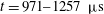
Figure 11. Displacement histories of the incident shock along and away from the interface (ISB and ISC), the transmitted shock, and the first and second triple points (TP1 and TP2), for the square (a), streamwise-rectangle (b), transverse-rectangle (c), forward-triangle (d), backward-triangle (e) and diamond (f). Here ‘ISB-up’ and ‘ISB-down’ denote the incident shock along the upstream and downstream interfaces respectively for the diamond. The straight lines are from the linear fitting and all the quantities are measured based on their own reference points.
For the square, as the incident shock moves along the upper surface (
 ${\it\theta}=90^{\circ }$
), a Mach stem, nearly normal to the interface, intersects the incident shock and the reflected shock at a triple point above the interface, as shown in figure 9(b). Such refraction is referred to as MRR (Abd-el Fattah & Henderson Reference Abd-el Fattah and Henderson1978a
). The shock–shock interaction between the transmitted shock and the refracted shock inside the volume induces the formation of the S1, S2, two triple points and shock
${\it\theta}=90^{\circ }$
), a Mach stem, nearly normal to the interface, intersects the incident shock and the reflected shock at a triple point above the interface, as shown in figure 9(b). Such refraction is referred to as MRR (Abd-el Fattah & Henderson Reference Abd-el Fattah and Henderson1978a
). The shock–shock interaction between the transmitted shock and the refracted shock inside the volume induces the formation of the S1, S2, two triple points and shock
 $n$
. Note that if we consider the transmitted shock as an incident shock, the wave pattern inside the volume is quite similar to the one occurring at a slow/fast interface which is called twin von Neumann refraction (TNR) (Abd-el Fattah & Henderson Reference Abd-el Fattah and Henderson1978b
). Under this circumstance, the refracted shock is regarded as the free precursor shock and the other shocks may have characteristics similar to corresponding ones at a slow/fast interface.
$n$
. Note that if we consider the transmitted shock as an incident shock, the wave pattern inside the volume is quite similar to the one occurring at a slow/fast interface which is called twin von Neumann refraction (TNR) (Abd-el Fattah & Henderson Reference Abd-el Fattah and Henderson1978b
). Under this circumstance, the refracted shock is regarded as the free precursor shock and the other shocks may have characteristics similar to corresponding ones at a slow/fast interface.
When the incident shock moves along the hypotenuse of the backward-triangle, the wave pattern of MRR occurs as presented in figure 10(a). The interaction of the transmitted shock and the refracted shock causes the emergence of the S1 and S2 inside the volume, as well as the appearance of the expansion waves at the interface. This type of wave system inside the volume has also been found at a slow/fast interface and is called free precursor refraction (FPR) (Jahn Reference Jahn1956; Abd-el Fattah et al. Reference Abd-el Fattah, Henderson and Lozzi1976; Abd-el Fattah & Henderson Reference Abd-el Fattah and Henderson1978b ). As the diffracted shock travels forwards, the wave pattern inside the volume changes, as shown in figure 10(b), which can be referred to as free precursor von Neumann refraction (FNR) at a slow/fast interface (Abd-el Fattah & Henderson Reference Abd-el Fattah and Henderson1978b ). Note that in the experimental work of Abd-el Fattah & Henderson (Reference Abd-el Fattah and Henderson1978b ), the wave pattern of bound precursor refraction (BPR) was found to be converted into FNR for a very weak group and into FPR for a weak group by changing the incident angle in each group. However, FNR and FPR were never observed within the same group even though they believed that FNR can convert into FPR. In our previous work (Zhai et al. Reference Zhai, Wang, Si and Luo2014a ), the wave patterns of FNR and FPR are experimentally observed in the same group and the transition from FNR to FPR was also found, which confirms the viewpoint proposed by Abd-el Fattah & Henderson (Reference Abd-el Fattah and Henderson1978b ). Moreover, in the numerical work of Henderson et al. (Reference Henderson, Colella and Puckett1991), the transitions of the wave patterns from BPR to FPR and then to FNR were observed within the same group. Unfortunately, there is no experimental support for this. In the present work, both FPR and FNR are also observed in the same case and FNR is found to be transformed from FPR, which provides the experimental evidence for the numerical results of Henderson et al. (Reference Henderson, Colella and Puckett1991). In other words, the reciprocal transformations between the wave patterns of FNR and FPR are experimentally found in our previous and present works. Note that in previous work, the different wave patterns were obtained by changing the incident angle for a fixed incident shock strength. In our work, however, the incident shock strength and the incident angle are both fixed, and the transition of the wave pattern happens during its evolution.
4.2. Velocity of characteristic waves
The positions of shocks and triple points are manually measured from the photographic results, and the corresponding
 $x{-}t$
diagrams are plotted in figure 11. The error bars are not included in the
$x{-}t$
diagrams are plotted in figure 11. The error bars are not included in the
 $x{-}t$
diagrams, because the errors of displacement are estimated to be less than 3 % for shocks and 8 % for triple points. For the square, the velocities of the incident shock along and away from the interface (ISB and ISC), the transmitted shock, as well as the two triple points (originating from the vertex of the interface) are indicated in figure 11(a). It is found that the ISC travels more quickly than the ISB which is disturbed by the expansion waves from the interface. The same treatments are carried out for two rectangular inhomogeneities and the corresponding results are presented in figures 11(b,c), respectively, and a similar conclusion to the square can be drawn. Figure 11(d) presents the velocity variations with time for the forward-triangle where there is only one triple point. The velocity of the ISB calculated from the linear fitting is
$x{-}t$
diagrams, because the errors of displacement are estimated to be less than 3 % for shocks and 8 % for triple points. For the square, the velocities of the incident shock along and away from the interface (ISB and ISC), the transmitted shock, as well as the two triple points (originating from the vertex of the interface) are indicated in figure 11(a). It is found that the ISC travels more quickly than the ISB which is disturbed by the expansion waves from the interface. The same treatments are carried out for two rectangular inhomogeneities and the corresponding results are presented in figures 11(b,c), respectively, and a similar conclusion to the square can be drawn. Figure 11(d) presents the velocity variations with time for the forward-triangle where there is only one triple point. The velocity of the ISB calculated from the linear fitting is
 $477.8~\text{m}~\text{s}^{-1}$
, which is exactly equal to the value computed from the expression of
$477.8~\text{m}~\text{s}^{-1}$
, which is exactly equal to the value computed from the expression of
 $V_{IS}/\!\cos (30^{\circ })$
, where
$V_{IS}/\!\cos (30^{\circ })$
, where
 $V_{IS}$
is the velocity of the incident shock and 30° is half of the forward-triangle interface vertex angle. This result confirms that the RRR does happen in this case. For the backward-triangle, due to the attenuation by the expansion waves, the velocity of the ISB is significantly decreased, as shown in figure 11(e). A similar feature to the backward-triangle is observed for the downstream interface of the diamond, as shown in figure 11( f).
$V_{IS}$
is the velocity of the incident shock and 30° is half of the forward-triangle interface vertex angle. This result confirms that the RRR does happen in this case. For the backward-triangle, due to the attenuation by the expansion waves, the velocity of the ISB is significantly decreased, as shown in figure 11(e). A similar feature to the backward-triangle is observed for the downstream interface of the diamond, as shown in figure 11( f).
For all cases, it is found that the initial shock speeds measured from the schlieren images coincide quite well with the values obtained by the piezoelectric pressure transducers, which indicates that the ambient air is almost not polluted by
 $\text{SF}_{6}$
. The physical properties of the ambient air ahead of and behind the shock are listed in table 1. The contamination of
$\text{SF}_{6}$
. The physical properties of the ambient air ahead of and behind the shock are listed in table 1. The contamination of
 $\text{SF}_{6}$
by air inside the volume, however, must be considered in the experiments. For the square, rectangles and backward-triangle, the interaction of the planar shock with the left surface can be regarded as a one-dimensional (1D) problem, and therefore the transmitted shock speed (
$\text{SF}_{6}$
by air inside the volume, however, must be considered in the experiments. For the square, rectangles and backward-triangle, the interaction of the planar shock with the left surface can be regarded as a one-dimensional (1D) problem, and therefore the transmitted shock speed (
 $V_{TS}$
-theo) and Mach number (
$V_{TS}$
-theo) and Mach number (
 $M_{TS}$
-theo) can be acquired by simply solving the 1D problem. The velocities of the transmitted shock for these four cases are first calculated assuming that both gases inside and outside the volume are pure. As listed in table 2, the theoretical values are all smaller than the measured counterparts, suggesting the impurity of the
$M_{TS}$
-theo) can be acquired by simply solving the 1D problem. The velocities of the transmitted shock for these four cases are first calculated assuming that both gases inside and outside the volume are pure. As listed in table 2, the theoretical values are all smaller than the measured counterparts, suggesting the impurity of the
 $\text{SF}_{6}$
inside the volume. Based on the experimental values of
$\text{SF}_{6}$
inside the volume. Based on the experimental values of
 $V_{TS}$
-exp, 1D gas dynamics theory is adopted to calculate the transmitted shock strength
$V_{TS}$
-exp, 1D gas dynamics theory is adopted to calculate the transmitted shock strength
 $M_{TS}$
-exp, and subsequently the physical properties of the mixture, such as molecular weight, density and sound speed, neglecting the faint variation of the specific heat ratio of the mixture. These quantities are listed in table 3, from which one can find that the
$M_{TS}$
-exp, and subsequently the physical properties of the mixture, such as molecular weight, density and sound speed, neglecting the faint variation of the specific heat ratio of the mixture. These quantities are listed in table 3, from which one can find that the
 $\text{SF}_{6}$
inside the volume is severely polluted by air, especially for the backward-triangle.
$\text{SF}_{6}$
inside the volume is severely polluted by air, especially for the backward-triangle.
Table 1. Physical properties of ambient air at
 $T_{0}=298~\text{K}$
and
$T_{0}=298~\text{K}$
and
 $p_{0}=101\,325~\text{Pa}$
. Here
$p_{0}=101\,325~\text{Pa}$
. Here
 ${\it\rho}_{e}$
and
${\it\rho}_{e}$
and
 ${\it\rho}_{2}$
are the densities of air ahead of and behind the incident shock, respectively, and
${\it\rho}_{2}$
are the densities of air ahead of and behind the incident shock, respectively, and
 $U_{f}$
is the post-shock flow velocity.
$U_{f}$
is the post-shock flow velocity.

Table 2. Comparison of the velocities of the incident shock (
 $V_{IS}$
) and the transmitted shock (
$V_{IS}$
) and the transmitted shock (
 $V_{TS}$
) between experiment and theoretical analysis from the 1D problem.
$V_{TS}$
) between experiment and theoretical analysis from the 1D problem.
 $M_{TS}$
is the Mach number of the transmitted shock. Note that the theoretical values are obtained based on the pure gases. The velocity unit is
$M_{TS}$
is the Mach number of the transmitted shock. Note that the theoretical values are obtained based on the pure gases. The velocity unit is
 $\text{m}~\text{s}^{-1}$
.
$\text{m}~\text{s}^{-1}$
.

Table 3. Physical properties of the test gas inside the volume at
 $T_{0}=298~\text{K}$
and
$T_{0}=298~\text{K}$
and
 $p_{0}=101\,325~\text{Pa}$
. Here
$p_{0}=101\,325~\text{Pa}$
. Here
 $m\,\%$
A
$m\,\%$
A
 $+$
$+$
 $n\,\%$
B denotes that the gas is the mixture of
$n\,\%$
B denotes that the gas is the mixture of
 $m\,\%$
A and
$m\,\%$
A and
 $n\,\%$
B (the mass fraction);
$n\,\%$
B (the mass fraction);
 $A^{+}$
is the post-shock Atwood number.
$A^{+}$
is the post-shock Atwood number.

Time variations of the angles between the initial horizontal interface and the trajectories of two triple points (
 ${\it\alpha}_{1}$
and
${\it\alpha}_{1}$
and
 ${\it\alpha}_{2}$
), as well as the refracted shock front (
${\it\alpha}_{2}$
), as well as the refracted shock front (
 ${\it\delta}$
) are given in figure 12 for the square, the rectangles and the forward-triangle, respectively. The schematic diagram of the refracted shock front and the trajectories of the triple points for the rectangular case are shown in figure 9(b). The error bars represent the uncertainty in manual measurements of the experimental results. It is found that for each case, the velocity and the moving direction of each triple point are nearly invariable and therefore the motion of the triple point can be regarded as self-similar or pseudo-stationary. In addition, the values of
${\it\delta}$
) are given in figure 12 for the square, the rectangles and the forward-triangle, respectively. The schematic diagram of the refracted shock front and the trajectories of the triple points for the rectangular case are shown in figure 9(b). The error bars represent the uncertainty in manual measurements of the experimental results. It is found that for each case, the velocity and the moving direction of each triple point are nearly invariable and therefore the motion of the triple point can be regarded as self-similar or pseudo-stationary. In addition, the values of
 ${\it\alpha}_{1}$
and
${\it\alpha}_{1}$
and
 ${\it\alpha}_{2}$
in the present work approach the counterparts of the triple points that occur outside the
${\it\alpha}_{2}$
in the present work approach the counterparts of the triple points that occur outside the
 $\text{N}_{2}$
volume in our previous work (Zhai et al.
Reference Zhai, Wang, Si and Luo2014a
), which once again illustrates the similarity between them even though there are some disparities between the velocities of two triple points. Moreover, for square and rectangular geometries, the value of
$\text{N}_{2}$
volume in our previous work (Zhai et al.
Reference Zhai, Wang, Si and Luo2014a
), which once again illustrates the similarity between them even though there are some disparities between the velocities of two triple points. Moreover, for square and rectangular geometries, the value of
 ${\it\delta}$
and the average values of
${\it\delta}$
and the average values of
 ${\it\alpha}_{1}$
and
${\it\alpha}_{1}$
and
 ${\it\alpha}_{2}$
are quite similar. The discrepancies of the velocity and the angle among these three cases may be attributed to the different concentrations of the gas components inside the volume.
${\it\alpha}_{2}$
are quite similar. The discrepancies of the velocity and the angle among these three cases may be attributed to the different concentrations of the gas components inside the volume.

Figure 12. Variation of angles
 ${\it\alpha}_{1}$
,
${\it\alpha}_{1}$
,
 ${\it\alpha}_{2}$
and
${\it\alpha}_{2}$
and
 ${\it\delta}$
for the square (a), streamwise-rectangle (b), transverse-rectangle (c) and forward-triangle (d). The angles are defined in figure 9.
${\it\delta}$
for the square (a), streamwise-rectangle (b), transverse-rectangle (c) and forward-triangle (d). The angles are defined in figure 9.
The angle
 ${\it\delta}$
can be deduced using the refractive index of the materials by
${\it\delta}$
can be deduced using the refractive index of the materials by
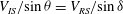 $V_{IS}/\!\sin {\it\theta}=V_{RS}/\!\sin {\it\delta}$
, where
$V_{IS}/\!\sin {\it\theta}=V_{RS}/\!\sin {\it\delta}$
, where
 $V_{RS}$
is the refracted shock speed (Henderson Reference Henderson1989). Approximately, the refracted shock has a speed equal to the vertical transmitted shock (Bates et al.
Reference Bates, Nikiforakis and Holder2007). Based on the values measured in the experiments, one can estimate the angle
$V_{RS}$
is the refracted shock speed (Henderson Reference Henderson1989). Approximately, the refracted shock has a speed equal to the vertical transmitted shock (Bates et al.
Reference Bates, Nikiforakis and Holder2007). Based on the values measured in the experiments, one can estimate the angle
 ${\it\delta}$
. For the square and rectangular cases, the incident angle
${\it\delta}$
. For the square and rectangular cases, the incident angle
 ${\it\theta}$
is considered to be 90°, and therefore
${\it\theta}$
is considered to be 90°, and therefore
 ${\it\delta}=\arcsin (V_{RS}/V_{IS})$
. The values of angle
${\it\delta}=\arcsin (V_{RS}/V_{IS})$
. The values of angle
 ${\it\delta}$
are calculated to be 28°, 28.1° and 28.5° for the square, streamwise-rectangle and transverse-rectangle, respectively, in reasonable agreement with the experimental measurements. Based on the geometrical relationship, as indicated in figure 13(a), one can deduce that
${\it\delta}$
are calculated to be 28°, 28.1° and 28.5° for the square, streamwise-rectangle and transverse-rectangle, respectively, in reasonable agreement with the experimental measurements. Based on the geometrical relationship, as indicated in figure 13(a), one can deduce that
 $V_{TS}=V_{TP2}\cos ({\it\alpha}_{2})$
, and
$V_{TS}=V_{TP2}\cos ({\it\alpha}_{2})$
, and
 $V_{RS}=V_{TP1}\sin ({\it\alpha}_{1}+{\it\delta})$
. From figures 11 and 12(a–c), it is found that the second triple point moves faster than the first triple point, and
$V_{RS}=V_{TP1}\sin ({\it\alpha}_{1}+{\it\delta})$
. From figures 11 and 12(a–c), it is found that the second triple point moves faster than the first triple point, and
 ${\it\alpha}_{1}+{\it\delta}<90^{\circ }-{\it\alpha}_{2}$
, which means that
${\it\alpha}_{1}+{\it\delta}<90^{\circ }-{\it\alpha}_{2}$
, which means that
 $V_{RS}<V_{TS}$
. In other words, the values of
$V_{RS}<V_{TS}$
. In other words, the values of
 ${\it\delta}$
computed are slightly overestimated if the
${\it\delta}$
computed are slightly overestimated if the
 $V_{RS}$
is substituted by the
$V_{RS}$
is substituted by the
 $V_{TS}$
. From the former expression, the angle
$V_{TS}$
. From the former expression, the angle
 ${\it\alpha}_{2}$
is calculated to be 30.2°, 29.2° and 32.9° for the square, streamwise-rectangle and transverse-rectangle cases, respectively. There is an almost 2° difference compared with the manual measurements, which is within the range of experimental error. From the latter expression and the hypothesis that the refracted shock speed is equal to the transmitted shock speed, the values of
${\it\alpha}_{2}$
is calculated to be 30.2°, 29.2° and 32.9° for the square, streamwise-rectangle and transverse-rectangle cases, respectively. There is an almost 2° difference compared with the manual measurements, which is within the range of experimental error. From the latter expression and the hypothesis that the refracted shock speed is equal to the transmitted shock speed, the values of
 ${\it\alpha}_{1}$
are calculated to be 33.1°, 33.9° and 30.5° for the square, streamwise-rectangle and transverse-rectangle, respectively. A larger discrepancy exists since each quantity is an approximation and the first two values are unsatisfactory because
${\it\alpha}_{1}$
are calculated to be 33.1°, 33.9° and 30.5° for the square, streamwise-rectangle and transverse-rectangle, respectively. A larger discrepancy exists since each quantity is an approximation and the first two values are unsatisfactory because
 ${\it\alpha}_{1}$
must be smaller than
${\it\alpha}_{1}$
must be smaller than
 ${\it\alpha}_{2}$
.
${\it\alpha}_{2}$
.

Figure 13. Sketch of angles of the top horizontal boundary with the refracted shock front (
 ${\it\delta}$
) and with the trajectories of the two triple points (
${\it\delta}$
) and with the trajectories of the two triple points (
 ${\it\alpha}_{1}$
and
${\it\alpha}_{1}$
and
 ${\it\alpha}_{2}$
).
${\it\alpha}_{2}$
).
 $V_{T}$
, the transmitted shock speed;
$V_{T}$
, the transmitted shock speed;
 $V_{R}$
, the refracted shock speed;
$V_{R}$
, the refracted shock speed;
 $V_{TP}$
, the triple point speed.
$V_{TP}$
, the triple point speed.

Figure 14. Comparison of normalized movements of the distorted interface for (a) the square and the rectangles and (b) the triangles and the diamond. Normalized height of the interface structures for (c) the square and the rectangles and (d) the triangles and the diamond.
For the forward-triangle volume, regular refraction happens at the hypotenuse, and
 ${\it\alpha}$
is defined as the angle between the trajectory of the triple point and the hypotenuse, as shown in figure 13(b). According to the refraction law and geometrical relation, one can obtain that
${\it\alpha}$
is defined as the angle between the trajectory of the triple point and the hypotenuse, as shown in figure 13(b). According to the refraction law and geometrical relation, one can obtain that
 $V_{IS}/\!\sin {\it\theta}=V_{RS}/\!\sin {\it\delta}=V_{TP}\sin ({\it\alpha}+{\it\delta})/\!\sin {\it\delta}$
. It is found from the schlieren images that the triple point nearly propagates along the angle bisector, and therefore the angle
$V_{IS}/\!\sin {\it\theta}=V_{RS}/\!\sin {\it\delta}=V_{TP}\sin ({\it\alpha}+{\it\delta})/\!\sin {\it\delta}$
. It is found from the schlieren images that the triple point nearly propagates along the angle bisector, and therefore the angle
 ${\it\alpha}$
can be approximately considered to be 30°. Thus, using the experimental values of velocities, the refraction angle
${\it\alpha}$
can be approximately considered to be 30°. Thus, using the experimental values of velocities, the refraction angle
 ${\it\delta}$
is computed from the above expression to be 26.6°, which is acceptable considering the experimental error. In fact, the assumption of
${\it\delta}$
is computed from the above expression to be 26.6°, which is acceptable considering the experimental error. In fact, the assumption of
 ${\it\alpha}$
equal to 30° is practicable since the experimental value of
${\it\alpha}$
equal to 30° is practicable since the experimental value of
 ${\it\alpha}$
is measured to be about 28°.
${\it\alpha}$
is measured to be about 28°.
5. Effect of initial interface shape on RMI
In order to illustrate the effect of initial interface shape on the development of RMI, the movements of the distorted interface and the interface height are presented. In addition, the behaviours of the vortex pair are analysed.
5.1. Interface features
Figure 14 gives the normalized movements of the distorted interface and the normalized interface height obtained from the experiments;
 $x_{l}$
and
$x_{l}$
and
 $x_{r}$
denote the leftmost and rightmost boundaries of the interface, as indicated in figure 15, and are normalized as
$x_{r}$
denote the leftmost and rightmost boundaries of the interface, as indicated in figure 15, and are normalized as
 $x_{l}^{\ast }=(x_{l}-x_{0})/L_{0}$
and
$x_{l}^{\ast }=(x_{l}-x_{0})/L_{0}$
and
 $x_{r}^{\ast }=(x_{r}-x_{0})/L_{0}$
, where
$x_{r}^{\ast }=(x_{r}-x_{0})/L_{0}$
, where
 $x_{0}$
is the initial leftmost position of the interface. As a result,
$x_{0}$
is the initial leftmost position of the interface. As a result,
 $x_{l}^{\ast }=0$
and
$x_{l}^{\ast }=0$
and
 $x_{r}^{\ast }=1$
indicate the quiescence of the leftmost and rightmost boundaries, respectively. The interface height (
$x_{r}^{\ast }=1$
indicate the quiescence of the leftmost and rightmost boundaries, respectively. The interface height (
 $h$
) is normalized by its initial height (
$h$
) is normalized by its initial height (
 $h^{\ast }=h/h_{0}$
). The characteristic time
$h^{\ast }=h/h_{0}$
). The characteristic time
 $t_{0}$
is calculated using the post-shock flow velocity
$t_{0}$
is calculated using the post-shock flow velocity
 $U_{f}$
, that is,
$U_{f}$
, that is,
 $t_{0}=L_{0}/U_{f}$
. For all cases, the errors of
$t_{0}=L_{0}/U_{f}$
. For all cases, the errors of
 $x_{l}^{\ast },x_{r}^{\ast }$
and
$x_{l}^{\ast },x_{r}^{\ast }$
and
 $h^{\ast }$
are estimated to be less than 3 % at early stages and 8 % at late stages, and the error bars are not included in the figures because of the data concentration.
$h^{\ast }$
are estimated to be less than 3 % at early stages and 8 % at late stages, and the error bars are not included in the figures because of the data concentration.

Figure 15. Schematic sketch of the distances measured for
 $\text{SF}_{6}$
square inhomogeneity.
$\text{SF}_{6}$
square inhomogeneity.
Table 4. Comparison of the normalized velocity of the leftmost boundary estimated from the linear fitting for six cases.

For all cases, the movements of the leftmost boundary (
 $x_{l}^{\ast }$
) are nearly steady for the range of time studied, as indicated in figures 14(a,b), and the corresponding normalized velocities are listed in table 4. It can be observed that the
$x_{l}^{\ast }$
) are nearly steady for the range of time studied, as indicated in figures 14(a,b), and the corresponding normalized velocities are listed in table 4. It can be observed that the
 $x_{l}^{\ast }$
moves with nearly the same velocity for the square, the rectangles and the backward-triangle due to similar initial shapes. A similar velocity of
$x_{l}^{\ast }$
moves with nearly the same velocity for the square, the rectangles and the backward-triangle due to similar initial shapes. A similar velocity of
 $x_{l}^{\ast }$
is also found for the forward-triangle and the diamond. For the rightmost boundary (
$x_{l}^{\ast }$
is also found for the forward-triangle and the diamond. For the rightmost boundary (
 $x_{r}^{\ast }$
), they are stationary before the shock passes through it, and afterwards different behaviours are found for different interfaces. For the square and the rectangles, the rightmost boundaries also move with nearly the same velocity at early stages. However, for the streamwise-rectangle in the following development, the backward movement of the rightmost boundary is observed. Note that the
$x_{r}^{\ast }$
), they are stationary before the shock passes through it, and afterwards different behaviours are found for different interfaces. For the square and the rectangles, the rightmost boundaries also move with nearly the same velocity at early stages. However, for the streamwise-rectangle in the following development, the backward movement of the rightmost boundary is observed. Note that the
 $x_{r}^{\ast }$
always indicates the farthest position of the interface. Taking the square, for example, as illustrated in figure 15, before the upstream vortex pair catches up with the downstream one, the
$x_{r}^{\ast }$
always indicates the farthest position of the interface. Taking the square, for example, as illustrated in figure 15, before the upstream vortex pair catches up with the downstream one, the
 $x_{r}^{\ast }$
denotes the boundary of the downstream vortex pair. Otherwise, the
$x_{r}^{\ast }$
denotes the boundary of the downstream vortex pair. Otherwise, the
 $x_{r}^{\ast }$
represents the boundary of the upstream vortex pair. For the streamwise-rectangle, however, after the downstream vortex pair is generated and before the upstream vortex pair catches up with it, the second downstream vortex pair is produced and becomes prominent while the downstream vortex pair gradually diffuses and becomes obscure. The boundary of the second downstream vortex pair is subsequently considered to be the measuring position, leading to the reversed motion of the
$x_{r}^{\ast }$
represents the boundary of the upstream vortex pair. For the streamwise-rectangle, however, after the downstream vortex pair is generated and before the upstream vortex pair catches up with it, the second downstream vortex pair is produced and becomes prominent while the downstream vortex pair gradually diffuses and becomes obscure. The boundary of the second downstream vortex pair is subsequently considered to be the measuring position, leading to the reversed motion of the
 $x_{r}^{\ast }$
. The normalized movements of the leftmost and rightmost boundaries from the numerical results of Bates et al. (Reference Bates, Nikiforakis and Holder2007) are also included in the figures, represented by solid and dashed lines. Compared with the present work, it is found that either the leftmost or rightmost interface moves relatively slowly, which may be attributed to the presence of the wire meshes and the characteristics of the continuous interface described above. It can be observed from figure 14(b) that, after the compression stage, the
$x_{r}^{\ast }$
. The normalized movements of the leftmost and rightmost boundaries from the numerical results of Bates et al. (Reference Bates, Nikiforakis and Holder2007) are also included in the figures, represented by solid and dashed lines. Compared with the present work, it is found that either the leftmost or rightmost interface moves relatively slowly, which may be attributed to the presence of the wire meshes and the characteristics of the continuous interface described above. It can be observed from figure 14(b) that, after the compression stage, the
 $x_{r}^{\ast }$
of the forward-triangle moves with a nearly constant velocity due to the generation of the downstream vortex pair. For the backward-triangle and the diamond, however, the
$x_{r}^{\ast }$
of the forward-triangle moves with a nearly constant velocity due to the generation of the downstream vortex pair. For the backward-triangle and the diamond, however, the
 $x_{r}^{\ast }$
moves quite slowly after the compression stage compared with the forward-triangle, because the rightmost boundary does not change much at early times. When the upstream vortex pair surpasses the downstream structure and becomes the measuring position, the
$x_{r}^{\ast }$
moves quite slowly after the compression stage compared with the forward-triangle, because the rightmost boundary does not change much at early times. When the upstream vortex pair surpasses the downstream structure and becomes the measuring position, the
 $x_{r}^{\ast }$
travels with a larger velocity.
$x_{r}^{\ast }$
travels with a larger velocity.
The variations of the normalized height
 $h^{\ast }$
of the interface for all cases are presented in figures 14(c,d). It is found that
$h^{\ast }$
of the interface for all cases are presented in figures 14(c,d). It is found that
 $h^{\ast }$
increases steadily from the beginning for the square and rectangular geometries due to the continuous rotation of the upstream vortex pair, and the larger the width–height ratio, the faster the growth of
$h^{\ast }$
increases steadily from the beginning for the square and rectangular geometries due to the continuous rotation of the upstream vortex pair, and the larger the width–height ratio, the faster the growth of
 $h^{\ast }$
. The variation of the normalized height from the computation of Bates et al. (Reference Bates, Nikiforakis and Holder2007), denoted by a solid line, is also shown here. Because the width–height ratio in the work of Bates et al. (Reference Bates, Nikiforakis and Holder2007) is 0.75, it is reasonable to find that its growth rate lies between the square and the transverse-rectangle (the width–height ratios for the square and the transverse-rectangle are 1 and 0.5, respectively). The rotation of the upstream vortex pair also leads to continuous increase of the
$h^{\ast }$
. The variation of the normalized height from the computation of Bates et al. (Reference Bates, Nikiforakis and Holder2007), denoted by a solid line, is also shown here. Because the width–height ratio in the work of Bates et al. (Reference Bates, Nikiforakis and Holder2007) is 0.75, it is reasonable to find that its growth rate lies between the square and the transverse-rectangle (the width–height ratios for the square and the transverse-rectangle are 1 and 0.5, respectively). The rotation of the upstream vortex pair also leads to continuous increase of the
 $h^{\ast }$
for the backward-triangle. However, for the diamond and forward-triangle, due to the effect of the initial interface shape, the invariability of the
$h^{\ast }$
for the backward-triangle. However, for the diamond and forward-triangle, due to the effect of the initial interface shape, the invariability of the
 $h^{\ast }$
is observed at the very early stage and then the
$h^{\ast }$
is observed at the very early stage and then the
 $h^{\ast }$
drops, especially for the forward-triangle in which the
$h^{\ast }$
drops, especially for the forward-triangle in which the
 $h^{\ast }$
always decreases within the time studied.
$h^{\ast }$
always decreases within the time studied.
From the comparison of the movements of the distorted interface and the variations of the interface features, it can be concluded that the initial interface shape has a large influence on interface morphology and characteristics after the shock impact. For the square and rectangular geometries, although the interface shapes are similar, the differences in interface scale result in diversity of interface morphology, such as the numbers of outward jets. In addition, the variation of the normalized height indicates that the larger the initial interface height, the smaller the relative change in height. For the forward-triangle and the backward-triangle with the same scale but different orientations, greater differences are found for the variations of the interface displacement and height, where the compressive effect is quite different.
5.2. Vorticity
During the shock–interface interaction, the rotational flow evolves on much longer timescales than that of the shock passage through the local non-uniformity and can therefore have important long-term effects on the structure and property of the flow field. The equation that governs the evolution of vorticity
 ${\it\omega}$
in an inviscid fluid can be expressed by
${\it\omega}$
in an inviscid fluid can be expressed by
 $$\begin{eqnarray}\frac{\text{D}{\it\omega}}{\text{D}t}=\frac{1}{{\it\rho}^{2}}(\boldsymbol{{\rm\nabla}}{\it\rho}\times \boldsymbol{{\rm\nabla}}p)+({\it\omega}\boldsymbol{\cdot }\boldsymbol{{\rm\nabla}})v-{\it\omega}(\boldsymbol{{\rm\nabla}}\boldsymbol{\cdot }v),\end{eqnarray}$$
where
 $\boldsymbol{{\rm\nabla}}{\it\rho}$
and
$\boldsymbol{{\rm\nabla}}{\it\rho}$
and
 $\boldsymbol{{\rm\nabla}}p$
stand for the density and pressure gradients, respectively, and
$\boldsymbol{{\rm\nabla}}p$
stand for the density and pressure gradients, respectively, and
 $v$
is the fluid velocity. It has been proved that the misalignment of the local pressure and density gradients is the primary source of vorticity generation during the shock–interface interaction (Ranjan, Oakley & Bonazza Reference Ranjan, Oakley and Bonazza2011).
$v$
is the fluid velocity. It has been proved that the misalignment of the local pressure and density gradients is the primary source of vorticity generation during the shock–interface interaction (Ranjan, Oakley & Bonazza Reference Ranjan, Oakley and Bonazza2011).
Figure 16 shows the diagrams of vorticity generation for the square, the forward-triangle and the diamond, where only the effects of the incident shock and the diffracted shock are emphasized for simplification. For the square, little vorticity is generated at the leftmost vertical interface where the pressure and density gradients are aligned. When the incident shock propagates along the horizontal upper interface, Mach reflection occurs, in which the Mach stem connects the incident shock with the interface. It is therefore the Mach stem that contributes the pressure gradient for the vorticity generation on the interface. However, the strength of the Mach stem is actually decaying as it moves forwards. If the variation of the Mach stem strength is neglected, a negative vorticity peak will be produced due to the near-orthogonality of the pressure and density gradients, and can be regarded as a constant value. As the diffracted shock moves along the rightmost interface, the vorticity amplitude is decreasing due to the gradual attenuation of the diffracted shock strength although the near-orthogonality of the pressure and density gradients is still maintained (Skews Reference Skews1967; Edwards Reference Edwards1983). For the upstream interfaces of the forward-triangle and the diamond, the pressure and density gradients are not orthogonal. At the downstream interfaces, although the diffracted shock strength decays, the orthogonality relationship is almost preserved. Therefore, it is difficult to estimate which vorticity amplitude is larger qualitatively. From the movements of the vortex pairs, it may be concluded that the vorticity deposited at the upstream and downstream interfaces is comparable.

Figure 16. Sketch maps of the vorticity generation on the boundaries for the square (a), forward-triangle (b) and diamond (c).
 $\boldsymbol{{\rm\nabla}}p$
, pressure gradient caused by the incident shock;
$\boldsymbol{{\rm\nabla}}p$
, pressure gradient caused by the incident shock;
 $\boldsymbol{{\rm\nabla}}p^{\prime }$
, pressure gradient caused by the diffracted shock.
$\boldsymbol{{\rm\nabla}}p^{\prime }$
, pressure gradient caused by the diffracted shock.
The circulation
 ${\it\Gamma}$
is an important quantity in the description of vortical flows. It is defined as a line integral of the velocity around a closed curve
${\it\Gamma}$
is an important quantity in the description of vortical flows. It is defined as a line integral of the velocity around a closed curve
 $L$
or is equal to the flux of vorticity through an open surface
$L$
or is equal to the flux of vorticity through an open surface
 $A$
bounded by the curve, that is,
$A$
bounded by the curve, that is,
 ${\it\Gamma}=\oint _{L}\boldsymbol{U}\boldsymbol{\cdot }\text{d}s=\int _{A}{\it\omega}\boldsymbol{\cdot }\text{d}\boldsymbol{S}$
. In previous studies several theoretical models have been proposed to predict the circulation (Ranjan et al.
Reference Ranjan, Oakley and Bonazza2011). In the following discussion, some models are adopted to estimate the circulation deposition on the interface and then the self-induced vortex speed. To calculate the circulation, the densities of the gases are needed in advance and therefore the forward-triangle and the diamond are ignored. Furthermore, for the backward-triangle, because the shock strength is greatly attenuated when the shock propagates along the hypotenuse and it is difficult to estimate the shock strength, the circulation deposition is also not considered here. For the square and the rectangles, as stated earlier, when the shock moves along the horizontal interface, the attenuation of the shock strength can be neglected. Consequently, only the circulation depositions on the horizontal interface in the square and rectangular cases are evaluated.
${\it\Gamma}=\oint _{L}\boldsymbol{U}\boldsymbol{\cdot }\text{d}s=\int _{A}{\it\omega}\boldsymbol{\cdot }\text{d}\boldsymbol{S}$
. In previous studies several theoretical models have been proposed to predict the circulation (Ranjan et al.
Reference Ranjan, Oakley and Bonazza2011). In the following discussion, some models are adopted to estimate the circulation deposition on the interface and then the self-induced vortex speed. To calculate the circulation, the densities of the gases are needed in advance and therefore the forward-triangle and the diamond are ignored. Furthermore, for the backward-triangle, because the shock strength is greatly attenuated when the shock propagates along the hypotenuse and it is difficult to estimate the shock strength, the circulation deposition is also not considered here. For the square and the rectangles, as stated earlier, when the shock moves along the horizontal interface, the attenuation of the shock strength can be neglected. Consequently, only the circulation depositions on the horizontal interface in the square and rectangular cases are evaluated.
The circulation model provided by Picone & Boris (Reference Picone and Boris1988) (the PB model) considers the baroclinic term to be the only source term for the vorticity on the half-plane of the bubble, and is based on the initial properties of the shocked and unshocked ambient gases, and the geometry. For the current rectangular geometry, the PB model may be written as
 $$\begin{eqnarray}{\it\Gamma}_{PB}\approx \frac{L_{0}}{V_{IS}}\frac{\boldsymbol{{\rm\nabla}}p}{{\it\rho}_{e}}\left(\frac{\boldsymbol{{\rm\nabla}}{\it\rho}}{{\it\rho}_{i}}\right),\end{eqnarray}$$
where
 ${\it\rho}_{i}$
and
${\it\rho}_{i}$
and
 ${\it\rho}_{e}$
are the initial densities of the interior and exterior gases, respectively.
${\it\rho}_{e}$
are the initial densities of the interior and exterior gases, respectively.
Yang, Kubota & Zukoski (Reference Yang, Kubota and Zukoski1994) numerically investigated the shock–cylinder interaction and proposed a circulation model (the YKZ model) assuming that the shock and the interface are non-deformable during shock–interface interaction. For the rectangular geometries in this study, the model can approximately be expressed by
 $$\begin{eqnarray}{\it\Gamma}_{YKZ}\approx \frac{2L_{0}}{V_{IS}}\frac{\boldsymbol{{\rm\nabla}}p}{{\it\rho}_{2}}\left(\frac{\boldsymbol{{\rm\nabla}}{\it\rho}}{{\it\rho}_{i}+{\it\rho}_{e}}\right),\end{eqnarray}$$
where
 ${\it\rho}_{2}$
is the post-shock flow density.
${\it\rho}_{2}$
is the post-shock flow density.
Based on the shock polar analysis, Samtaney & Zabusky (Reference Samtaney and Zabusky1994) proposed a model (the SZ model) to predict the deposited circulation on the assumption that the discontinuous interface is composed of many straight segments. The circulation
 ${\it\Gamma}$
can be written as
${\it\Gamma}$
can be written as
 $$\begin{eqnarray}{\it\Gamma}_{SZ}\approx \frac{2{\it\gamma}^{1/2}}{{\it\gamma}+1}(1-{\it\eta}^{-1/2})(1+M^{-1}+2M^{-2})(M-1)\sin {\it\theta},\end{eqnarray}$$
where
 ${\it\gamma}$
can be thought of as the average of the specific heat ratios of two gases, and
${\it\gamma}$
can be thought of as the average of the specific heat ratios of two gases, and
 ${\it\eta}$
is the density ratio of two gases.
${\it\eta}$
is the density ratio of two gases.
From (5.2)–(5.4), the deposited circulation
 ${\it\Gamma}$
on the half-plane is estimated as listed in table 5. It is found that the values predicted by the PB model are the smallest ones among all the models, while the predictions by the YKZ and SZ models coincide well with each other. After the circulation
${\it\Gamma}$
on the half-plane is estimated as listed in table 5. It is found that the values predicted by the PB model are the smallest ones among all the models, while the predictions by the YKZ and SZ models coincide well with each other. After the circulation
 ${\it\Gamma}$
is known, it is possible for us to deduce the self-induced velocity (
${\it\Gamma}$
is known, it is possible for us to deduce the self-induced velocity (
 $V_{v}^{\prime }$
) of the vortex pair through the simplified relation between
$V_{v}^{\prime }$
) of the vortex pair through the simplified relation between
 $V_{v}^{\prime }$
and
$V_{v}^{\prime }$
and
 ${\it\Gamma}$
:
${\it\Gamma}$
:
 $V_{v}^{\prime }={\it\Gamma}/(2{\rm\pi}L_{v})$
, where
$V_{v}^{\prime }={\it\Gamma}/(2{\rm\pi}L_{v})$
, where
 $L_{v}$
is the vortex spacing of the upstream vortex pair, as defined in figures 3–5. The vortex spacing
$L_{v}$
is the vortex spacing of the upstream vortex pair, as defined in figures 3–5. The vortex spacing
 $L_{v}$
and the horizontal position of the vortex core
$L_{v}$
and the horizontal position of the vortex core
 $X_{v}$
, both normalized by the initial width
$X_{v}$
, both normalized by the initial width
 $L_{0}$
, are measured from the schlieren images and shown in figure 17, in which the error bars represent the uncertainty. The self-induced speeds of the vortex core,
$L_{0}$
, are measured from the schlieren images and shown in figure 17, in which the error bars represent the uncertainty. The self-induced speeds of the vortex core,
 $V_{v}^{\prime }$
, obtained by these models are listed in table 5. It is found that both the maximum circulation and subsequently the maximum
$V_{v}^{\prime }$
, obtained by these models are listed in table 5. It is found that both the maximum circulation and subsequently the maximum
 $V_{v}^{\prime }$
are achieved for the streamwise-rectangle while the minimum ones are achieved for the transverse-rectangle, which is closely associated with the length of the integral path.
$V_{v}^{\prime }$
are achieved for the streamwise-rectangle while the minimum ones are achieved for the transverse-rectangle, which is closely associated with the length of the integral path.
Table 5. Comparison of the circulation
 ${\it\Gamma}$
and the self-induced velocity
${\it\Gamma}$
and the self-induced velocity
 $V_{v}^{\prime }$
of the vortex pair for different models. The units of
$V_{v}^{\prime }$
of the vortex pair for different models. The units of
 $L_{v}$
,
$L_{v}$
,
 ${\it\Gamma}$
and
${\it\Gamma}$
and
 $V_{v}^{\prime }$
are mm,
$V_{v}^{\prime }$
are mm,
 $\text{m}~\text{s}^{-2}$
and
$\text{m}~\text{s}^{-2}$
and
 $\text{m}~\text{s}^{-1}$
, respectively.
$\text{m}~\text{s}^{-1}$
, respectively.


Figure 17. Time variation of the vortex core
 $X_{v}$
in the streamwise direction, and the vortex spacing
$X_{v}$
in the streamwise direction, and the vortex spacing
 $L_{v}$
in the spanwise direction for the square (a), streamwise-rectangle (b), transverse-rectangle (c) and backward-triangle (d).
$L_{v}$
in the spanwise direction for the square (a), streamwise-rectangle (b), transverse-rectangle (c) and backward-triangle (d).
The vortex velocity
 $V_{v}$
, considering the post-shock flow velocity (
$V_{v}$
, considering the post-shock flow velocity (
 $U_{f}$
) for heavy inhomogeneity, is defined as
$U_{f}$
) for heavy inhomogeneity, is defined as
 $V_{v}=U_{f}-V_{v}^{\prime }$
. Table 6 shows the vortex velocity predicted by these models, together with the experimental measured ones. It is found that these three models can reflect the circulation deposition to some extent although the models underestimate the values. Note that in experiments, the vortex velocity is measured from the upstream vortex pair. However, the self-induced velocity
$V_{v}=U_{f}-V_{v}^{\prime }$
. Table 6 shows the vortex velocity predicted by these models, together with the experimental measured ones. It is found that these three models can reflect the circulation deposition to some extent although the models underestimate the values. Note that in experiments, the vortex velocity is measured from the upstream vortex pair. However, the self-induced velocity
 $V_{v}^{\prime }$
is obtained from the models based on the assumption that the vorticity generated at the surface is deposited in one vortex pair, which will definitely overestimate
$V_{v}^{\prime }$
is obtained from the models based on the assumption that the vorticity generated at the surface is deposited in one vortex pair, which will definitely overestimate
 $V_{v}^{\prime }$
and consequently underestimate the vortex velocity (for heavy inhomogeneity, the velocity induced by the vorticity is in the opposite direction to the post-shock flow velocity). Therefore it is reasonable to find the smallest vortex velocity for the streamwise-rectangle and the largest value for the transverse-rectangle.
$V_{v}^{\prime }$
and consequently underestimate the vortex velocity (for heavy inhomogeneity, the velocity induced by the vorticity is in the opposite direction to the post-shock flow velocity). Therefore it is reasonable to find the smallest vortex velocity for the streamwise-rectangle and the largest value for the transverse-rectangle.
Table 6. Quantitative values of the vortex core speed
 $V_{v}$
measured from the experiments and circulation models for the square, streamwise-rectangle, transverse-rectangle and backward-triangle.
$V_{v}$
measured from the experiments and circulation models for the square, streamwise-rectangle, transverse-rectangle and backward-triangle.

In addition, Rudinger & Somers (Reference Rudinger and Somers1960) proposed a model (the R–S model) to predict the vortex velocity by assuming that the gaseous cylinder is fully developed into a vortex pair after the shock acceleration. In the R–S model, the vortex velocity
 $V_{v}$
is defined as
$V_{v}$
is defined as
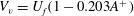 $V_{v}=U_{f}(1-0.203A^{+})$
, where
$V_{v}=U_{f}(1-0.203A^{+})$
, where
 $A^{+}$
is the post-shock Atwood number. The velocities of the vortex pair predicted by the R–S model for the square, two rectangles and the backward-triangle are listed in table 6 (gas contamination is considered). It is found that the R–S model also underestimates the vortex velocity for the same reason stated above. For the backward-triangle, the R–S model provides a better prediction for vortex speed because only one developed vortex pair is generated in this case. From the comparison, one can conclude that the circulation models mentioned above and the R–S model can, at least for current study, provide a rough prediction of the vortex velocity.
$A^{+}$
is the post-shock Atwood number. The velocities of the vortex pair predicted by the R–S model for the square, two rectangles and the backward-triangle are listed in table 6 (gas contamination is considered). It is found that the R–S model also underestimates the vortex velocity for the same reason stated above. For the backward-triangle, the R–S model provides a better prediction for vortex speed because only one developed vortex pair is generated in this case. From the comparison, one can conclude that the circulation models mentioned above and the R–S model can, at least for current study, provide a rough prediction of the vortex velocity.
6. Conclusions
As an extension of our previous work on the light polygon (Zhai et al.
Reference Zhai, Wang, Si and Luo2014a
), the primary goal of this work is to explore the shock refraction phenomenon at a fast/slow interface and the effect of the initial interface shape on the RMI through dealing with the interaction of a planar shock wave with six different
 $\text{SF}_{6}$
polygons surrounded by air, including a square, two rectangles, two triangles and a diamond. By restricting the soap film with thin pins,
$\text{SF}_{6}$
polygons surrounded by air, including a square, two rectangles, two triangles and a diamond. By restricting the soap film with thin pins,
 $\text{SF}_{6}$
polygons with different geometries are formed. Then the interface morphologies and characteristics, such as the displacements of the interfaces and the height induced by the shock impact, are acquired from the experiments based on the high-speed schlieren technique. It is found that the thin pins have a limited effect on the wave pattern and the interface evolution at early times, but they affect the interface morphology slightly at late stages, especially when the upstream interface passes through them.
$\text{SF}_{6}$
polygons with different geometries are formed. Then the interface morphologies and characteristics, such as the displacements of the interfaces and the height induced by the shock impact, are acquired from the experiments based on the high-speed schlieren technique. It is found that the thin pins have a limited effect on the wave pattern and the interface evolution at early times, but they affect the interface morphology slightly at late stages, especially when the upstream interface passes through them.
When the planar shock strikes the air/
 $\text{SF}_{6}$
gas interfaces, both RRR and MRR phenomena are observed. The shock–shock interaction inside the volume greatly increases the complexity of the wave pattern. If the transmitted shock is regarded as an incident shock, the irregular wave patterns of FPR, FNR and TNR, which occurred at a slow/fast interface in previous work, are all observed in the present work and FPR is found to be converted into FNR which experimentally confirms the previous numerical results of Henderson et al. (Reference Henderson, Colella and Puckett1991). In our previous work (Zhai et al.
Reference Zhai, Wang, Si and Luo2014a
), the transition of the wave patterns from FNR to FPR was also experimentally observed. In other words, the reciprocal transitions between the wave patterns of FNR and FPR are experimentally verified in our previous and present works. Further, the velocities of the characteristic waves and the triple points are measured from experiments, and the results indicate that the motions of the shocks and triple points are self-similar or pseudo-stationary.
$\text{SF}_{6}$
gas interfaces, both RRR and MRR phenomena are observed. The shock–shock interaction inside the volume greatly increases the complexity of the wave pattern. If the transmitted shock is regarded as an incident shock, the irregular wave patterns of FPR, FNR and TNR, which occurred at a slow/fast interface in previous work, are all observed in the present work and FPR is found to be converted into FNR which experimentally confirms the previous numerical results of Henderson et al. (Reference Henderson, Colella and Puckett1991). In our previous work (Zhai et al.
Reference Zhai, Wang, Si and Luo2014a
), the transition of the wave patterns from FNR to FPR was also experimentally observed. In other words, the reciprocal transitions between the wave patterns of FNR and FPR are experimentally verified in our previous and present works. Further, the velocities of the characteristic waves and the triple points are measured from experiments, and the results indicate that the motions of the shocks and triple points are self-similar or pseudo-stationary.
In our previous work (Zhai et al. Reference Zhai, Wang, Si and Luo2014a ), emphasis was placed on the wave patterns and little attention was paid to the effect of the initial interface shape on the RMI. In this work, as well as the wave patterns, the influence of the initial interface on the RMI is also examined, which can be observed from the interface morphology and the interface characteristics. In the square and two rectangular geometries, the remarkable feature is the formation of the vortex pairs from the upstream and downstream corners, and the former ultimately dominates the flow field for each case. In the light square inhomogeneity, however, only one upstream vortex pair is generated and no obvious downstream vortex pair is formed. In the heavy forward-triangle and the diamond, two vortex pairs are produced from the apexes, whereas in the light cases, the phase reversal occurs and the inward jet eventually pierces the downstream interface. Quantitatively, the normalized movements of the distorted interface and the normalized interface height are obtained and compared with the previous work of Bates et al. (Reference Bates, Nikiforakis and Holder2007). For the square and rectangular geometries, due to the differences in width–height ratio, the processes of the shock focusing and shock–shock interaction are different, resulting in changes in the outward jet and vortex pair formation. The initial width–height ratio also has a great influence on the development of the interface height. For two triangles, the different interface orientations lead to a larger discrepancy in the interface velocities and the variations of the interface characteristics. Moreover, the characteristics of the vortex core, including the vortex velocity and the vortex spacing, are experimentally measured, and several theoretical models are adopted to estimate the circulation deposition on the interface and then the vortex velocity to compare with the experimental ones. The results show that although the models underestimate the vortex velocity, they can still provide a rough prediction.
The present results can be used to validate the numerical codes or theoretical models for shock–interface interactions, and also enrich the database of interface morphology and wave pattern in the shock–interface studies. More interface shapes, test gases and shock strengths will be involved to further investigate the shock refraction phenomenon and the effect of interface shape on the RMI development. It should be noted that the effects of the soap film membrane and the thin pins should be considered. For quantitative analysis, especially for turbulent mixing at late stages, advanced diagnostic techniques of the flow should be employed.
Acknowledgements
This work is supported by the National Natural Science Foundation of China (11302219, 11272308), the China Postdoctoral Science Foundation (BH2090050031) and the Fundamental Research Funds for Central Universities (WK2090050020, WK2320000020).
Supplementary movies
Supplementary movies are available at http://dx.doi.org/10.1017/jfm.2015.257.


 Open access