


I. INTRODUCTION
Lateral patterning of thin films is essential for the fabrication of integrated circuits and other microdevices. A typical patterning sequence includes thin film deposition, resist application, lithographic patterning, etching, and resist removal. This series of steps is time consuming, can lower the quality of the deposited material and/or interface, and can introduce registry misalignment between patterned layers. Deposition processes that lead to self-directed lateral patterning during film growth are highly sought to lower costs and improve performance of devices.
Examples of selective area epitaxy (SAE) for III–V and II–VI semiconductors are prevalent in the metal–organic chemical vapor deposition (MOCVD) community. MOCVD SAE has been demonstrated for most of the III–V and II–VI semiconductors including GaAs, Reference Heinecke, Brauers, Grafahrend, Plass, Putz, Werner, Weyers, Luth and Balk1,Reference Fukui, Ando, Tokura and Toriyama2 GaN, Reference Zang and Chua3 InAs, Reference Bjork, Schmid, Breslin, Gignac and Riel4 and ZnSe. Reference Yamazaki, Chang, Cho, Sekiguchi and Yao5 This ability to laterally pattern III–V and II–VI semiconductors in a single growth step has led to advances in microelectronics, Reference Hartmann, Bertin, Rolland, Laugler and Semeria6,Reference Levitin, Hess and Prausnitz7 optoelectronics, Reference Azoulay, Bouadma, Bouley and Dugrand8 and photonics Reference Nelson, Dias, Bassett, Dunham, Verma, Miyake, Wiltzius, Rogers, Coleman, Li and Braun9 technology. In MOCVD of III–V and II–VI semiconductors, selectivity is typically achieved by applying oxide or nitride masks that force SAE on exposed semiconductor regions. The higher sticking coefficient for III–V or II–VI MOCVD precursors on semiconductor surfaces versus oxide or nitride surfaces is the generally accepted mechanism for selectivity. By controlling super-saturation via precursor partial pressures and working near equilibrium conditions, growth can be preferentially sustained on only the semiconductor surfaces. Reference Bhat10 Under proper growth conditions, selectivity between semiconductors and the oxide surface can be sufficiently high to completely preclude nucleation on the oxide surface and permit epitaxial growth through even three-dimensional oxide templates. Reference Nelson, Dias, Bassett, Dunham, Verma, Miyake, Wiltzius, Rogers, Coleman, Li and Braun9
Selective chemical vapor deposition (CVD) of other materials using other mechanisms is also possible. For example, selective silicon homoepitaxy can be favored over growth on patterned SiO2 surfaces by using hydrogen's preferential etching of strained silicon–silicon (Si–Si) bonds. By adjusting the SiH4 to H2 delivery ratio, nucleation can be prevented on nonepitaxial surfaces, like SiO2, where the Si–Si bonds are more strained. Reference Boland and Parsons11,Reference Yu, Gulari and Kanicki12 In CVD of metal films, surface reactivity is used to achieve selectivity. Selective deposition of tungsten films from WF6 is possible because semiconductor surfaces decompose the precursor molecule to initiate nucleation while oxide surfaces are unreactive toward the precursor. Reference Gladfelter13,Reference Hampdensmith and Kodas14 Patterning of metal catalysts is used for the selective deposition of semiconductor nanowires Reference Liang, Chen, Hwang, Chen, Hung and Chen15 and carbon nanotubes. Reference Fan, Chapline, Franklin, Tombler, Cassell and Dai16 Focused ion beams have also been used to “direct-write” epitaxial patterns of III–V semiconductors on crystalline substrates. Reference Nishiyama, Kim, Numata and Pak17
Selectivity is less common in physical vapor deposition (PVD) like molecular beam epitaxy (MBE) because elemental precursor sources (Ga, Al, As, etc.,) have higher sticking coefficients than their organometallic precursor analogues [Ga(CH3)3, Al(CH3)3, AsH3, etc.,], minimizing the differences in surface interactions. The most studied PVD process has been the selective area growth of GaAs by MBE at high growth temperatures and low gallium fluxes. Reference Allegretti, Inoue and Nishinaga18,Reference Suzuki, Shimoda, Okada and Kawabe19 Several approaches have been introduced to improve the reliability and growth rates of this selective area MBE process, including the use of activated species, Reference Sugaya, Okada and Kawabe20 focused ion beams, Reference Cho, Hachiro, Abe and Pak21 and precursor flux pulsing. Reference Nishinaga and Bacchin22 Selectivity with other PVD techniques, like sputtering, has been reported, but these typically require a narrow process window of deposition rate and substrate temperature. Reference Lee, Tsai, Chen, Huang and Chung23
In this paper, we describe a new MBE process for the SAE growth of MgO epilayers on gallium nitride surfaces. The ability to grow oxide epilayers over selective areas while retaining high crystalline quality is significant as the patterning of epitaxial oxide films often requires a hard-mask approach involving multiple processing steps. Reference Karthik, Damodaran and Martin24 In general, the epitaxial growth of oxides on wide-gap semiconductors has been studied in detail by us Reference Paisley, Losego, Gaddy, Tweedie, Collazo, Sitar, Irving and Maria25−Reference Losego, Mita, Collazo, Sitar and Maria31 and others Reference Chen, Hlad, Gerger, Gila, Ren, Abernathy and Pearton32–Reference Ihlefeld, Brumbach and Atcitty38 and has contemporary importance in the development of new high frequency and high power microelectronic devices for wireless communication and power conditioning. Reference Yifeng, Jacob-Mitos, Moore and Heikman39–Reference Doolittle, Namkoong, Carver and Brown41 This new processing technique uses surface chemistry patterning to direct the selective growth of MgO epilayers. A simple change in the GaN's surface chemistry to Cl-termination is found to prevent sticking of the Mg precursor and inhibit growth. Various surface characterization techniques are applied to further understand the selective growth mechanisms, and lateral patterns of MgO epilayers with micrometer resolution are demonstrated.
II. EXPERIMENTAL PROCEDURES
GaN epilayers (1.2 μm thick) deposited via cold-walled MOCVD on (0001) sapphire substrates using an AlN buffer layer were used as growth surfaces for MBE of MgO. Using a N2 diluent gas with triethylgallium, trimethylaluminum, and ammonia precursors, GaN was MOCVD grown under mass transport limited conditions. Reference Collazo, Mita, Schlesser and Sitar42,Reference Mita, Collazo, Rice, Dalmau and Sitar43 Final GaN growth surfaces had an (0001) Ga-face polarity orientation.
To control surface chemistry, GaN films were treated with either a concentrated 12 M HCl dip for 5 min (“HCl treatment”) or a 1:99 (by volume) ratio of 32 M HF:DI (deionized) water (“HF treatment”) for 5 min. Treatment times as short as 1 min appeared to be equally effective, and HCl treatments without HF treatments also prevented film growth. For selective area patterning, the entire surface received an “HF treatment,” a patterned polymer mask was lithographically applied, and the remaining exposed surface was given an “HCl treatment.” The polymer mask was then removed by sonicating in acetone for 2–5 min, and the GaN film was loaded into our oxide MBE.
All GaN substrates were thermally desorbed at 500 °C for ≥10 min in ultra high vacuum (UHV) at a pressure <5 × 10⁻⁸ Torr to further remove contaminants. A Perkin-Elmer 435 MBE system (PerkinElmer Inc., Waltham, Massachusetts) was used to deposit MgO epilayers. Reference Craft, Ihlefeld, Losego, Collazo, Sitar and Maria28,Reference Losego, Craft, Paisley, Mita, Collazo, Sitar and Maria29 Magnesium metal (99.98% purity filings from Alfa Aesar, Haverhill, Massachusetts) was sublimed from a Perkin-Elmer effusion cell containing a pyrolytic BN crucible. The metal flux was calibrated with a quartz crystal microbalance (Inficon XTM/2 Deposition Monitor, Inficon, Bad Ragaz, Switzerland) prior to substrate introduction via a loadlock. Most growths were conducted at relatively low metal fluxes of ∼5 × 10¹³ atoms cm−2/s−1, which corresponds to about 0.05 monolayers (MLs) of Mg per second. This Mg flux requires an effusion cell temperature between 340 and 360 °C depending on the crucible charge. Ultra-high purity oxygen was supplied as the oxidant via a 45 cm long stainless steel tube aimed at the substrate. The oxygen delivery rate was regulated with a UHV leak valve and monitored with an ion gauge attached to the opposing chamber wall. The desired oxygen partial pressure was set prior to growth, and growth was then initiated by the opening of the Mg effusion cell. Due to O2 gettering at the walls, the oxygen flux was continuously adjusted during the initial 5 min of growth until a steady-state pressure was achieved. Substrates were mechanically fastened to a molybdenum transfer puck using molybdenum clips. The molybdenum puck was radiation-heated by using a Ta filament. Reflection high energy electron diffraction (RHEED) patterns were collected in situ with a Perkin-Elmer Φ 20-330 analog HEED gun system projected on a phosphor screen and digitally captured with a k-Space acquisition system (kSA 400, K-Space Associates, Inc., Dexter, Michigan). Sample temperature was monitored with a Raytek IR pyrometer (Marathon Series) focused on the molybdenum puck.
MgO film thickness was measured ex situ with a Dektak profilometer (Bruker Nano Surfaces, Tucson, Arizona) using the step edge created by the molybdenum fastening clips. X-ray diffraction (XRD) patterns were collected with a Bruker AXS D-5000 diffractometer equipped with a High-Star area detector (Bruker AXS, Madison, Wisconsin). Images of the static contact angle for water droplets on various GaN surfaces were captured with a Ramé-Hart goniometer (RAME-HART, Succasunna, New Jersey) and analyzed with the DROPimage CA software. Patterned epilayers were imaged with a Hitachi S3200N scanning electron microscope (SEM; Hitachi, Tokyo, Japan) equipped with an Oxford energy dispersive x-ray spectrometer (EDS; Oxford Instruments, Abingdon, UK) for elemental analysis.
X-ray photoelectron spectroscopy (XPS) measurements were carried out in a surface analysis chamber (base pressure <1.0 × 10⁻¹⁰ Torr) using a VG hemispherical spectrometer and a dual-anode x-ray source. Al Kα radiation (1486.6 eV) was used for this experiment. The spectrometer was operated at a constant pass energy of 50 eV for survey scans, and 20 eV for detailed core level scans. XPS data were analyzed using IGOR Pro (Wavemetrics), and peak fitting, where applied, was accomplished using Voigt peak shapes.
III. RESULTS AND DISCUSSION
A. Demonstration of SAE
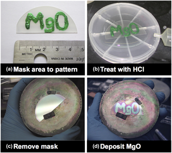
In Fig. 1, we demonstrate the general process for SAE of MgO epilayers on Ga-face (0001) GaN surfaces. First, the entire GaN surface is treated with 1:99 HF:H2O (5 min), and then the regions where deposition is desired are masked [here with a green lacquer for visibility, Fig. 1(a)]. Next, the sample is immersed in concentrated HCl for 5 min and rinsed with DI water [Fig. 1(b)]. The mask is then removed by sonication in acetone, leaving no visible pattern on the surface [Fig. 1(c)]. Finally, an MgO film is deposited by MBE at high growth temperatures (here at 400 °C) and low deposition rates [here at 6 × 10¹³ Mg atoms cm−2/s−1, 3 × 10⁻⁶ Torr O2, ∼0.4 nm/min]. The MgO film selectively grows where the GaN surface has not been exposed to HCl. In the following sections, we show that this prevention of film growth is due to a surface layer of Cl adatoms. The film seen in Fig. 1(d) is ∼75 nm thick (3 h of growth). Under these conditions and extended deposition time, some lateral growth from the non-HCl treated area is observed. This is consistent with other SAE processes where epitaxial lateral overgrowth occurs. Reference Nam, Bremser, Zheleva and Davis44

FIG. 1. Demonstration of MgO SAE process: (a) mask region for epitaxial growth with polymer, (b) expose patterned wafer to concentrated hydrochloric acid, (c) remove mask with acetone, and (d) selectively grow MgO by MBE.
B. Evaluation of SAE process window
To evaluate the SAE process window, MgO films were deposited on “HCl treated” and “HF treated” GaN surfaces over a range of substrate temperatures (200–450 °C) at a constant Mg flux [5 × 10¹³ atoms/(cm−2/s−1)] and oxygen partial pressure (6 × 10⁻⁶ Torr). All depositions were conducted for at least 45 min. Deposition rates derived from profilometry measurements of the film's final thickness are reported in Fig. 2. Immediately evident is a lower net deposition rate for all HCl treated GaN surfaces under the conditions explored. As discussed in theoretical work by Geneste et al. Reference Geneste, Morillo and Finocchi45,Reference Geneste, Morillo and Finocchi46 and our own experimental work, Reference Losego, Craft, Paisley, Mita, Collazo, Sitar and Maria29 adsorption-controlled growth of MgO is not dependent on a single component. Depending on the growth conditions, the Mg flux, the O2 flux, or both can be used to regulate film growth rates. The relative difference in incident Mg flux and Mg re-evaporation rate helps to delineate these different regimes. Using the equilibrium vapor pressure of Mg at 200 °C, we estimate a Mg re-evaporation rate from the surface of ∼1013 atoms cm−2/s−1 using the Hertz–Kundsen equation. The re-evaporation rate rises to ∼1015 atoms cm−2/s−1 at 250 °C. Reference Losego, Craft, Paisley, Mita, Collazo, Sitar and Maria29 Because these experiments use an incident Mg flux of ∼5 × 10¹³ atoms cm−2/s−1, Mg re-evaporation fluxes exceed incident fluxes over most of the growth conditions explored in Fig. 2. Under these growth conditions, MgO growth rate depends on both the Mg flux and the O2 flux. Reference Losego, Craft, Paisley, Mita, Collazo, Sitar and Maria29

FIG. 2. Growth rates for MgO on GaN surfaces undergoing either an HF (red circles) or HCl (blue squares) treatment prior to film deposition.
Regardless of surface chemistry, MgO growth with low Mg fluxes will eventually be kinetically prohibited by high Mg re-evaporation rates at high substrate temperatures. This critical temperature is ∼450 °C for the HF treated GaN surface but is 150 °C lower (300 °C) for the HCl treated surface. This reduction in critical temperature suggests a difference in the sticking coefficients for each surface. The optimal SAE growth conditions occur within the temperature range that provides the largest contrast in growth rates on the two surfaces. For the Mg and O2 fluxes studied here, this optimal SAE temperature range is between 300 and 350 °C.
C. Crystallinity of SAE MgO films on GaN
To evaluate the crystalline quality of these MgO films, we use the optimal parameters found in Sec. III. B to selectively deposit MgO films onto a GaN surface that is half exposed to an HCl treatment and half exposed to an HF treatment. Optimal growth conditions of 350 °C, 5 × 10¹³ Mg atoms cm−2/s−1, and oxygen partial pressures of 3 × 10⁻⁶ are used. As shown in Fig. 3(a), the film is visibly detectable on the HF treated side (right) but no film is visible on the HF + HCl treated side (left). Films on the HF treated GaN surface measure 60 nm in thickness (measured using profilometry of the step edge created by blocked deposition from the “clip” holding the substrate to the transfer puck). In-plane XRD patterns are collected from both the HCl treated and HF treated regions and reported in Figs. 3(b) and 3(c), respectively. MgO deposited on the HF treated surface shows only evidence of the 111 in-plane reflection (observed as a single spot on our XRD's area detector) indicative of (111) MgO||(0001) GaN epitaxy and consistent with our prior reports. Reference Paisley, Gaddy, LeBeau, Shelton, Biegalski, Christen, Losego, Mita, Collazo, Sitar, Irving and Maria26,Reference Craft, Ihlefeld, Losego, Collazo, Sitar and Maria28 In the HCl treated region, no diffraction peaks for MgO are detected. Because MgO deposition will be epitaxial, XRD is sensitive to MgO layers as thin as ∼5 nm. Thus, the absence of a diffraction peak strongly suggests nearly zero deposition on the HCl treated surface. We further collected x-ray reflectivity (XRR) data on a PANalytical Empyrean system with the results displayed in the inset of Fig. 3(b). XRR shows no detectable deposition on the HCl treated sample. Based on simulations of the XRR signal, this technique should be sensitive to the continuous MgO film with a thickness of ≥1 nm. Thus, we conclude that any deposition is <1 nm. However, as discussed later, we cannot fully eliminate the possible presence of a MgCl x surface layer.

FIG. 3. (a) Image of a selectively grown MgO epilayer on GaN. Region labeled “Clip” is where the fastener held the wafer in the MBE chamber during deposition and no deposition occurs. Inset shows the original masking pattern; mask was removed prior to deposition. (b) and (c) are XRD patterns collected after MBE growth of MgO epilayers (nominally 60 nm thick) on this treated GaN surface. (b) XRD collected from the left side receiving HF + HCl treatments, and (c) XRD collected from the right side receiving only an HF treatment. Inset of (b) shows XRR data demonstrating no detectable deposition on the HCl treated surface.
D. Investigation of the mechanism for SAE
We have conducted a series of tests to understand both the surface chemistry and surface morphology of the HF and HCl treated GaN substrates with the intention of isolating the mechanism for SAE. In Fig. 4, we present representative atomic force microscope (AFM) scans from a comprehensive study of the surface morphology of GaN under a variety of treatments. This study revealed no noticeable difference in the surface morphology after any chemical treatment. For example, in Fig. 4, both treated and untreated 5 μm × 5 μm AFM scans have an average RMS roughness of 0.67 nm. Based on these results, we eliminate the surface morphology as a root cause for the observed difference in the sticking coefficient.

FIG. 4. AFM images of GaN surfaces (a) as-grown and (b) after “HCl treatment.” (c) Water contact angle on GaN surfaces after various surface treatments.
Next, we macroscopically assessed surface energy using water contact angle measurements. These results are summarized in Fig. 4(c). As grown, MOCVD GaN epilayers have a contact angle of ∼68°, likely indicative of hydrophobic carbon contamination. Treatment in a 1% HF solution for 5 min lowers the contact angle to ∼23°. In contrast, exposure of the as-grown GaN surface to concentrated HCl for 5 min provides an even lower contact angle of ∼10°. Repetition of this experiment provided similar results, suggesting a clear change in the surface energy between HF and HCl treated GaN surfaces. Because no change in the surface morphology is detected, we conclude that this change in surface energy is a result of a change in surface chemistry.
XPS was used to probe the surface's chemical composition after various chemical treatments. Survey scans, presented in Fig. 5(a), show no significant differences in the chemistry of an “HF treated” and “HCl treated” GaN surface. However, high resolution XPS scans across the Cl 2p shell's binding energy reveal clear photoemission from the “HCl treated” surface [Fig. 5(b)]. Integration of this peak indicates the surface concentration of Cl to be equal to about 1 ML of adatoms. For “HF treated” GaN surfaces, the Cl concentration is near zero, with any detectable levels likely coming from cross-contamination during our etch process. These results are consistent with prior findings. Wet chemical etches with HF and HCl are known to help in removing surface oxides and carbon contaminants with only minor changes to the surface morphology. Residual F and Cl atoms have been previously detected on GaN by surface spectroscopy after HF and HCl treatments, respectively. Reference Lee, Donovan, Gila, Overberg, Mackenzie, Abernathy and Wilson47–Reference Tracy, Mecouch, Davis and Nemanich50

FIG. 5. XPS spectra of GaN surfaces exposed to either an “HCl treatment” (red) or “HF treatment” (blue): (a) survey scans and (b) high resolution scans of the Cl 2p photoemission lines. Spectra are offset for clarity.
As a complementary control experiment, we also considered treatment in another strong acid, HNO3. GaN surfaces exposed for 5 min to concentrated HNO3 (16 M) exhibited identical deposition rates to HF treated GaN surfaces. This control experiment helps to eliminate acidic protons, which are undetectable by XPS, as a source for deposition prevention, leaving passivation via surface chlorination as the most likely mechanism.
Based on these findings, we propose that a ML of Cl adatoms is the source of the observed changes to the sticking coefficient during MgO growth. At this point, we are unable to fully clarify the binding state of this Cl ML on the GaN surface. While we expect GaN surfaces to be Ga terminated Reference Smith, Feenstra, Greve, Neugebauer and Northrup51,Reference Zywietz, Neugebauer and Scheffler52 and GaCl2 to be a thermodynamically favored product, Reference Barin53 XPS scans of the Ga 3d photoemission line have been inconclusive in revealing a clear Ga–Cl bond. A small shoulder at high binding energies is consistently observed for many GaN surfaces. This shoulder could be attributed to either surface oxygen or surface chlorine and is difficult to differentiate. Mg is also known to readily react with Cl to form stable MgCl2 surfaces. Reference Koranyi, Magni and Somorjai54 Thus, the surface-bound Cl atoms may also react with the incident Mg flux to form a MgCl x surface layer. Regardless of its exact chemistry, it is apparent that the surface-bound Cl is reducing the surface adsorption of the Mg and/or O2 precursor species. This reduced surface resonance time likely precludes the dissociation of molecular O2, which is known to be a rate limiting step in reactive MgO film growth. Reference Geneste, Morillo and Finocchi45,Reference Geneste, Morillo and Finocchi46
E. Retainment of Cl adatoms on the surface of MgO epilayers
Our prior work Reference Paisley, Losego, Gaddy, Tweedie, Collazo, Sitar, Irving and Maria25,Reference Paisley, Gaddy, LeBeau, Shelton, Biegalski, Christen, Losego, Mita, Collazo, Sitar, Irving and Maria26 using hydroxyls as surfactants to energetically stabilize the (111) surface of MgO epilayers during film growth made us curious as to whether the Cl adatoms could show similar surfactant behavior. Growth of atomically smooth (111) MgO epilayers is essential for good insulating performance and so has great technological relevance. Reference Paisley, Losego, Gaddy, Tweedie, Collazo, Sitar, Irving and Maria25 Several parallels could be made between the hydroxide and chloride behaviors including the observation that hydroxylated (111) MgO epilayers have a slower growth rate than nonhydroxylated epilayers. In this study, we used high Mg and O2 fluxes to force growth on the “HCl treated” surfaces. GaN surfaces with both an “HCl treatment” and “HF treatment” were simultaneously exposed to identical growth conditions [475 °C growth temperature, Mg flux of 4 × 10¹⁴ atoms/(cm−2/s−1), and 3 × 10⁻⁶ Torr O2] and their surface chemistries were studied by XPS and RHEED. Films were grown until the MgO epilayers reached a nominal thickness of ∼50 nm on the HF treated GaN surface.
The XPS survey scans presented in Fig. 6(a) indicate no detectable emission lines for the underlying GaN substrate for either of the MgO||GaN structures. This absence of substrate emission indicates that the MgO films on both surfaces are fully coalesced. Surprisingly, MgO films grown on “HCl treated” GaN surfaces still show detectable levels of Cl. This Cl emission is verified in the high-resolution XPS scan shown in Fig. 6(b). Because no additional Cl is provided during growth and no Cl signal is detected in the HF treated sample, we conclude that the original ML of surface-bound Cl takes part in the MgO growth process. During growth, this Cl ML must remain, at least partially, on the MgO surface, similar to the behavior of other film growth “surfactants.” Reference Paisley, Losego, Gaddy, Tweedie, Collazo, Sitar, Irving and Maria25,Reference Egelhoff, Chen, Powell, Stiles, McMichael, Judy, Takano and Berkowitz55

FIG. 6. XPS spectra collected from nominally 50 nm thick MgO epilayers grown on “HCl treated” (red) and “HF treated” (blue) GaN surfaces under “high” Mg flux conditions: survey spectra and high-resolution scan of Cl 2p photoemission line. Spectra are offset for clarity.
The use of Cl as a surfactant for (111) MgO surfaces is consistent with prior observations. Koranyi et al. have reported Cl to be labile and show preferential surface residence when growing Mg metal on top of MgCl2 crystals. Reference Koranyi, Magni and Somorjai54 Presumably, this is driven by a reduction of free energy that accompanies a MgCl2-like skin. To accurately substantiate Cl's surfactant ability, detailed ab initio studies are needed to compare the stability of a chlorinated (111) MgO surface to modified or unmodified (100) MgO surfaces. While this is beyond the scope of the current work, a simple calculation using bulk thermodynamic data Reference Barin53 shows that MgCl2 (ΔG formation = −530 kJ/mol) is more stable than MgO (ΔG formation = −525 kJ/mol) at the growth temperatures explored, providing some credence to the Cl surfactant hypothesis.
We have also used in situ RHEED analysis to study film growth under these “high” Mg flux conditions. Images of RHEED patterns collected for MgO films grown on HCl-treated and HF-treated GaN at high flux rates are shown in Fig. 7. Here, the RHEED patterns were collected for equivalent flux-time doses. MgO film growth is retarded on HCl-treated GaN as evidenced by less charging in the RHEED patterns. Both RHEED signals become “spotty” diffraction patterns almost immediately and no intensity oscillations are detected. These observations indicate the immediate formation of a rough growth surface consistent with Volmer–Weber (island) film growth. These results imply that pyramidal MgO crystals with (100) facets nucleate and grow on the (0001) GaN surface for both HF- and HCl-treated GaN at high growth rates, consistent with the surfactant-less equilibrium habit of MgO epilayers grown in vacuum. Reference Paisley, Gaddy, LeBeau, Shelton, Biegalski, Christen, Losego, Mita, Collazo, Sitar, Irving and Maria26,Reference Craft, Collazo, Losego, Mita, Sitar and Maria27

FIG. 7. Images of RHEED patterns during high flux growth on HF-treated (a–c) and HCl-treated (d–f) GaN surfaces. Growth conditions on both surfaces are identical. Images are collected at the same flux-time doses and thicknesses are referenced to the calibrated MgO thickness for growth on HF-treated GaN.
While discouraging, these results do not completely preclude Cl's utility as a surfactant. A continual supply of Cl is likely needed to maintain sufficient surface concentrations to influence growth mode. We see a similar need to provide a constant H2O surfactant flux when growing smooth, –OH terminated (111) MgO epilayers on GaN. Reference Paisley, Losego, Gaddy, Tweedie, Collazo, Sitar, Irving and Maria25 If the H2O flux is removed at any point during film growth, the surfactant effect is lost and a rapid transition from 2D to 3D growth mode occurs. Indeed, the concentrations of Cl are noticeably lower on the surface of the thick MgO films [Fig. 6(b)] than on the surface of the starting “HCl treated” GaN [Fig. 5(b)], suggesting that a Cl2 supply in the MBE growth environment is needed to achieve the surfactant effect.
F. Implementation of SAE MgO on GaN for lateral patterning
Finally, we report on pattern resolution for the MgO SAE process. Here, we have used standard photolithographic micropatterning techniques to selectively chlorinate the GaN surface. MgO films with a thickness of ∼55 nm were grown selectively via MBE on these chlorinated patterns. Representative SEM images of the final patterned films grown from these surfaces are shown in Fig. 8. Note that MgO patterns appear bright in the SEM images due to sample charging. This compositional identification is further confirmed by an EDS line scan analysis shown in Fig. 9. Because film growth was conducted outside of a cleanroom, dust particles are present. All patterns retain sharp, well-defined edges, and features as small as 3 μm are easily replicated in the MgO epilayers, suggesting that even finer resolution is likely possible.

FIG. 8. (a–c) SEM images of MgO SAE on GaN using photolithographic patterning to define regions of surface modification. White areas are MgO epilayers while dark areas are the GaN surface.
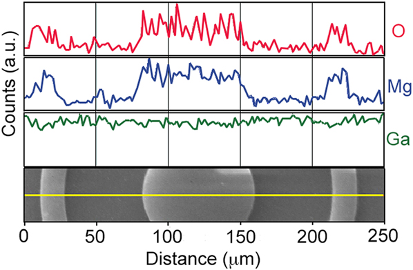
FIG. 9. EDS line scans of the O and Mg K-shells and Ga L-shell characteristic x-rays across a MgO SAE pattern. The corresponding SEM image from which the EDS line scans were collected is shown at the bottom.
IV. CONCLUSIONS
A new approach for the selective area epitaxy of MgO films on GaN surfaces is presented. Immersion of a GaN surface into an HCl solution is found to prevent the deposition of MgO films under certain MBE growth conditions (high substrate temperatures and low incident Mg fluxes). A ML of Cl adatoms was the only detectable difference in the surface structure between the “HCl treated” GaN surfaces that blocked deposition and control surfaces that allowed MgO deposition. Based on XPS studies of the surface chemistry during MgO film growth in combination with prior studies of MgO surface adsorption kinetics, we conclude that the adsorbed chlorine ML forms an energetically stable (0001) GaN surface with a reduced sticking coefficient for Mg and O2 precursors. When this chlorine passivation layer is applied in a lateral pattern to a GaN surface, epitaxial MgO films preferentially nucleate and grow in the unchlorinated regions. Lateral patterning of MgO epilayers with micrometer feature sizes is demonstrated, although even better resolution is likely possible. Because few processes exist for the selective deposition of oxide materials, this technique has important ramifications for simplifying microelectronics processing, especially in the quickly growing industries of solid-state lighting, microwave electronics, and power conditioning.
ACKNOWLEDGMENTS
The authors acknowledge funding from the ONR MURI project Epitaxial Multifunctional Materials and Applications (2004-0779), the NSF Graduate Fellowship program, and Georgia Tech startup funds. Sandia National Laboratories is a multi-program laboratory managed and operated by Sandia Corporation, a wholly owned subsidiary of Lockheed Martin Corporation, for the U.S. Department of Energy's National Nuclear Security Administration under contract DE-AC04-94Al85000. We also thank Jan Genzer for access to his contact angle goniometer and data analysis software.


 Open access