I. INTRODUCTION
A three-dimensional (3D) representation of a video can be achieved by multiplexing two views of the same scene (Stereo format), recorded by two different cameras into one stereoscopic display. While the Stereo format is currently dominating the 3D video market, the development of services such as 3D television (3DTV) or free viewpoint television (FTV) creates a need for a more fluid representation of the scene, which can only be obtained if more than two views are multiplexed simultaneously on the 3D display. The multiview video + depth (MVD) format allows to have a large number of views at the receiver side, with a reduced coding cost compared to the multiview video (MVV) format. This format is promising and thus, standardization activities are currently focusing on drafting an High Efficiency Video Coding (HEVC)-based [Reference Tech, Wegner, Chen and Yea1] (3D-HEVC) and an AVC-based [Reference Rusanovsky, Chen, Zhang and Suzuki2] (3D-AVC) 3D video coding standard that is able to exploit all the spatial, temporal, inter-view, and inter-component (between texture and depth) redundancies in an MVD video.
In MVD, depth cameras complement ordinary texture cameras. Each texture video has an associated depth video, accounting for objects distance to the camera. After encoding and transmission, the reconstructed texture videos and depth videos can be fed into a view synthesizer that, using the geometric information of depths, generates the required number of intermediate views. Depth frames, commonly called depth maps, have unique characteristics that make them inherently less costly to code than texture frames.
Numerous tools found in the literature attempt to efficiently code depth maps. Some tools exploit redundancies between texture and depth in order to achieve this goal. These inter-component coding tools are, however, mostly designed to improve depth coding in Inter mode. In this work, we introduce a new coding tool for depth map coding in Intra configurations, where the inheritance of the texture Intra mode for a currently coded depth prediction unit or PU (in HEVC) is driven by a metric computed solely on the reference texture PU. This metric quantifies a criterion that exploits the statistical dependency between the texture and depth Intra modes. We study two criteria in this work: GradientMax and DominantAngle.
The rest of this paper is organized as follows: Section II presents different tools found in the literature specifically designed to improve the coding efficiency of depth videos. Section III details the motivation and presents the general concept of our proposed tool using the GradientMax criterion. Section IV presents the experimental setting and the coding gains obtained with this criterion. In order to further increase coding efficiency, we propose the DominantAngle criterion as an appropriate replacement to GradientMax. The motivation behind the development of the DominantAngle criterion and its general concept are detailed in Section V. Section VI presents and interprets the results using DominantAngle. Section VII concludes this paper while underlining the possibilities for future work.
II. STATE OF THE ART
A) Intra coding in 3D-HEVC
3D-HEVC uses the Intra coding mode introduced in HEVC [Reference Bross, Han, Ohm, Sullivan, Wang and Wiegand3] to exploit spatial correlations in the same slice as the currently coded PU. In HEVC, 33 prediction directions are used, also known as angular Intra modes, as shown in Fig. 1. Three non-directional Intra modes exist as well: the DC, the Planar, and for chroma components, a mode that signals the use of the same Intra mode as the luma component. The most recent test model of 3D-HEVC at the time of writing this paper (test model 3 [Reference Tech, Wegner, Chen and Yea1]), adds to these modes four new ones dedicated for depth coding. These modes, called depth modeling modes (DMM) [Reference Schwarz, Bartnik and Bosse4], try to predict the depth PU using a Platelet approximation.

Fig. 1. Angular Intra prediction modes in HEVC.
The most probable mode (MPM) tool, introduced in HEVC, reduces the cost of signaling the Intra mode. Each PU has at most two MPM candidates, which are the Intra modes of the PU above and the PU to the left of the coded PU. If the best Intra mode of the coded PU matches one of the MPM candidates, only a flag signaling the use of an MPM candidate and another flag signaling which MPM candidate matches the best mode are transmitted. This effectively avoids coding the best Intra mode itself and reduces the Intra mode signaling bitrate.
B) Depth video coding technologies
In order to increase the coding efficiency of MVD data, new coding tools, specifically designed for depth maps, must be used. They can be listed in three categories, as done in [Reference Mora, Valensize, Jung, Pesquet-Popescu, Cagnazzo and Dufaux5]. First, there are tools that exploit the inherent characteristics of depth maps such as their piece-wise planar behavior. This is specifically exploited by the aforementioned DMM coding tool. Second, there are tools that optimize the depth coding for the quality of the synthesized views (SVs) such as in [Reference Lee, Oh and Lim6] or in [Reference Tech, Schwarz, Muller and Wiegand7]. Finally, there are tools that exploit the correlations between texture and depth. In this category, we find the motion parameter inheritance (MPI) [Reference Schwarz, Bartnik and Bosse4] tool, where the partitioning structure and the motion vectors of the co-located texture coding unit (CU) are considered for direct inheritance in a currently coded depth CU. This motion information sharing can also be performed using inter-layer prediction in the scalable extension of H.264/AVC (SVC) [Reference Tao, Chen, Hannuksela, Wang, Gabbouj and Li8]. A coding tool is also developed where depth blocks are forced to be coded in SKIP mode according to the temporal correlation in the associated texture video [Reference Lee, Wey and Park9]. Depth blocks can also be forced to be coded in SKIP mode simply when the co-located texture block is coded in SKIP, as proposed in [Reference Kim, Ortega, Lai, Tian and Gomila10]. It is also possible to use the texture information to design new spatial transforms to code the depth maps more efficiently, as proposed in [Reference Daribo, Tillier and Pesquet-Popescu11]. Furthermore, in [Reference Maitre, Shinagawa and Do12], the depth map and texture image are jointly coded to decrease their redundancy and to provide a rate distortion (RD)-optimized global bitrate allocation. Finally, in [Reference Liu, Lai, Tian and Chen13], a new in-loop filter, called trilateral filter, is used to filter the depth component based on the similarity of the co-located pixels in the video frame.
Few coding tools in this category are designed to improve depth Intra coding. Having an efficient Intra coding mode is nevertheless important, as the spatial prediction associated with the different Intra directions allows us to correctly represent the dynamics of the PU when motion estimation fails. This is especially true in depth PU coding considering the simple piece-wise planar behavior of depth maps. Having an efficient Intra coding mode requires to have a technique to reduce the bitrate used to signal the Intra mode (or direction), which takes a large portion of the total depth bitrate. Such a technique is proposed in [Reference Bang, Yoo and Nam14], where the Intra mode of the co-located texture PU is added to the MPM candidate list for the currently coded depth PU. However, if the MPM list is already full, one of the two available candidates is necessarily removed in order to replace it with the inherited texture Intra mode, otherwise an additional bit is required for signaling the MPM index. This substitution is not always the best choice if there is little dependency between the texture and depth Intra modes; i.e. a potentially good MPM candidate might be replaced by a bad one.
In this work, we propose a novel method that drives this texture Intra mode inheritance using one of two proposed criteria. In an earlier work [Reference Mora, Jung, Pesquet-Popescu and Cagnazzo15], the first criterion GradientMax was introduced, but was not tested in a full 3D codec. We perform this test in this paper, and also present the second criterion: DominantAngle.
III. PROPOSED INTRA MODE INHERITANCE TOOL AND GRADIENTMAX CRITERION
A). Preliminary study
When analyzing a depth video bitstream coded in an Intra configuration using HTM-0.3 (reference software for 3D-HEVC) and the same testing conditions as described in Section IV-A, we find that the Intra mode signaling (including DMMs) represents 25% of the total depth bitrate. It is the element that has the largest coding cost in depth videos. Hence, there is much to gain if the bitrate needed to code the depth Intra modes is reduced. The MPM tool reduces this cost. In an MVD system, a depth video is always associated with a texture video, and we can further improve the efficiency of the MPM tool if we exploit the dependency between the Intra modes of texture and depth. In practice, this means that an additional MPM candidate or predictor, which is the Intra mode of the corresponding texture PU, is added to the MPM candidate list of a depth PU. However, texture and depth Intra modes do not always match.
Further experiments under the same configuration and testing conditions have shown that when comparing a coded depth map to its associated coded texture frame, the Intra mode of a depth PU, chosen by the rate distortion optimization (RDO) process, matches the Intra mode of its co-located texture PU in average 18% of the time, as shown in Table 1.
Table 1. Percentage of PUs where the texture Intra mode matches the one in depth for various tested sequences.
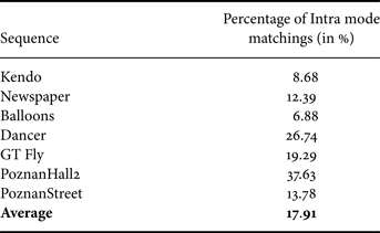
These experiments also show that the matching occurs mostly in areas where there are sharp edges in texture. Indeed, a sharp edge in texture defines a dominant geometric structure, which is likely to exist in depth as well. Since Intra modes are highly directional, they closely follow this structure, and hence, the texture and depth Intra modes are likely to be the same, as shown in Fig. 2. This figure shows a texture PU and its co-located depth PU. The texture PU is composed of parts of a red object and a background. Since the object and the background have different depth levels, they will be represented in the depth PU as two different regions seperated by a sharp edge. A specific Intra direction (represented by arrows), parallel to this edge, will be chosen for the texture PU by RDO, as it is the direction that most accurately describes the geometric structure of the PU. Since this structure also exists in depth, the same Intra direction will be chosen by the depth RDO.

Fig. 2. Geometric partitioning and resulting Intra direction of a texture and depth PU caused by the presence of an edge.
Consequently, if the texture Intra mode inheritance is only done for depth PUs whose co-located texture PU contains sharp edges, the Intra mode signaling bitrate for these PUs will be reduced. The remaining depth PUs, to which the texture Intra mode is irrelevant, will not be impacted.
Figure 3 shows a depth map and its associated texture frame from the Kendo sequence, which is studied in our test set. This frame is coded using the same Intra configuration and testing conditions as in the previous experiments. In Fig. 3(c–e), all PUs are coded in Intra. PUs marked in light green in Fig. 3(c) are PUs that contain sharp edges detected by gradient estimation in texture. PUs marked in yellow in Fig. 3(d) are PUs where the depth Intra mode matches the texture Intra mode. For the maximal coding efficiency, the texture Intra mode inheritance should only be performed on the yellow PUs, but those are not known a priori by the decoder. The light green PUs are known, and we can see that the light green and yellow PUs approximately superpose, hence validating our assumption.

Fig. 3. Kendo texture frame and associated depth map analysis.
Note that some Intra mode matchings can be exploited in smooth areas, but it is not very beneficial to do so. Indeed, Fig. 3(e) shows the coding cost of Intra CUs in the Kendo depth map. The RD cost computed at the encoder for each CU is mapped to an intensity value. Hence, a lighter red color indicates a CU that costs more to code than a darker colored CU. We can see that the smooth areas are cheap to code so we cannot expect much gains if we reduce the Intra mode signaling at this level.
B) Proposed algorithm
For a currently coded depth PU, a corresponding texture PU T ref needs to be found. It is generally the co-located PU except when the texture CU is more finely partitioned than the depth CU: T ref is set as the top left PU, and when the depth CU is more finely partitioned than the texture CU: the latter is set as T ref for all depth partitions (PUs). These three cases are shown in Fig. 4.

Fig. 4. Definition of the corresponding texture PU T ref for a currently coded depth PU in our algorithm.
Then, a metric is computed on T ref and compared to a fixed constant threshold. If the computed metric is higher than that threshold, then the texture Intra mode is inherited and added to the MPM candidate list of the depth PU. Otherwise, no inheritance is performed. In Section III-A, we show that the texture and depth Intra modes match in PUs where there are sharp edges in texture. Hence, the metric has to quantify the presence of an edge in T ref .
To compute the metric, we perform a Sobel filtering on T ref . We choose the Sobel filter because it is a simple and effective edge detector. Other edge detection filters such as the Prewitt or Canny filters can also be used. The Sobel filter output is composed of two gradient matrices G x and G y . From these matrices, we can compute the gradient module matrix M as follows:
The metric is set as the maximum value of this gradient module matrix (GradientMax). It is a measure of the sharpness of the edges present in the texture PU, and can therefore be used to drive the inheritance.
If the computed metric is larger than the specified threshold, the texture Intra mode is inherited and is inserted into the MPM candidate list. However, that list can contain at most two candidates. If there is only one spatial candidate in the list (the modes of the two spatial neighbors are identical, or one of the two neighbors is not Intra coded or falls outside the slice), the texture Intra mode is added, and the resulting list is sorted in ascending order of Intra modes. The modes are sorted as shown in Fig. 1 according to the prediction direction. The vertical and horizontal directions have the lowest modes (1 and 2 in the figure), followed by the diagonal directions, and finally the finer angles that have the highest Intra modes. If there are two spatial candidates in the list, then the texture Intra mode always replaces the second, and the resulting list is sorted in ascending order of Intra modes. The different steps of the algorithm are depicted in Fig. 5.

Fig. 5. Algorithm of our proposed tool.
Note that the proposed method is intended to be integrated into a full 3D-HEVC codec. The resulting bitsream is decodable and so, the edge detection in Step 2 is performed on a reconstructed T ref , because the depth decoder does not have access to original texture samples. This is possible, since we assume that the texture frame is coded before the depth frame, meaning the depth encoder also has access to reconstructed texture samples.
Furthermore, we observe that the proposed method is somewhat similar to the MPI method described in Section II-B, which can be used in the case of Inter coded PUs. However, MPI is not driven by a criterion as in our algorithm (the motion vector is always inherited), and as we show in the following, imposing conditions on the inheritance is the most relevant part of the proposed method. Note that MPI and our algorithm can be used together, as also shown in the experimental section.
IV. EXPERIMENTAL RESULTS WITH THE GRADIENTMAX CRITERION
A) Experimental setting
In a previous work [Reference Mora, Jung, Pesquet-Popescu and Cagnazzo15], we had implemented our tool in HM-3.3, the HEVC reference software. We used a traditional “2D” video codec to compress depth sequences. Exploiting inter-component correlations was entirely left to the proposed Intra mode inheritance tool. Moreover, the depth coding mode was selected to minimize the depth distortion, which is not the optimal strategy. A first new contribution of the present paper is that we implement our tool in a full 3D codec: HTM-0.3 [16], based on the HM-3.0 reference software for HEVC. It includes multiview functionalities (inter-view prediction) and other inter-component coding tools, on top of which our tool is added. One of the most important functionalities of the software is the view synthesis optimization (VSO) tool. Indeed, in HTM-0.3, the distortion induced by a currently evaluated coding mode for a depth PU, and which is used in the RDO process to compute the cost of that mode, is not evaluated on the depth itself, but on a SV. This is the optimal strategy for depth coding mode selection.
The MPEG 3DV community defined some common test conditions (CTCs) [Reference Rusanovsky, Muller and Vetro17] to evaluate new coding tools. We respect all of these conditions, except that we evaluate our tool in an all-Intra configuration, where all the frames of all the views (texture and depth) are coded in Intra. This should not be surprising, since our method is intended to improve Intra coding. Gains on Inter images are still possible because, resulting from the use of our tool, better Intra reference frames are used for Inter prediction, and because PUs can be coded in Intra mode in these frames as well. However, gains in the Inter configuration are smaller since our method has less chances to be selected.
Configuration parameters are the following: 8-bit internal processing, CABAC entropy coding, disabling the loop filter for depth coding, DMM and MPI tools enabled for depth coding, and a GOP size and Intra period set to 1 to signal an Intra configuration. 35 Intra modes are considered for both texture and depth components. PU sizes range from 64 × 64 to 4 × 4. In addition, the Residual QuadTree (RQT), the mode-dependant directional transform (MDDT) and the Intra smoothing (IS) tools are enabled, which results in an efficient Intra configuration, on top of which our tool is added. We consider four QPs for texture: 25, 30, 35, and 40 and their respective QPs for depth: 34, 39, 42, and 45 to conform to CTCs.
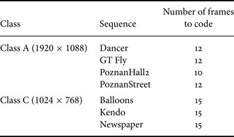
We test our tool on the seven sequences defined in the CTCs, which consist of four 1920 × 1088 and three 1024 × 768 resolution sequences, as shown in Table 2. The length of these sequences is 10 seconds each, but we choose to only code half a second of video to speed up the simulations. We believe that this is acceptable since multiple sequences are considered, with different types of content, and because an all-Intra configuration is considered anyway, which means the coding of each frame is independant from the coding choices made in the previous frame. To conform to CTCs, a three-view case is considered where three texture views and three depth views are encoded for each sequence. After encoding, three views are synthesized between the center and the left view, and another three between the center and the right view, making a total of six SVs per sequence. The Bjontegaard delta rate (BD-Rate) metric [18] is used to evaluate gains on the depth and SV components. The reference consists of HTM-0.3 with the same configuration but in which our tool is disabled.
Table 2. Sequences in test set.
To obtain the average gain for depth, the BD-Rate for each of the three-coded depth views is computed using the rate and PSNR values associated with the coding of that depth view. Then the three gains are averaged. To obtain the average gain for SVs, the BD-Rate for each of the six synthesized views is computed using the PSNR value of the SV and the combined rate of all three coded depth views, since all of them are involved in the synthesis of each intermediate view. To compute the PSNRs of the SVs, uncompressed texture and depth views are used to synthesize 6 intermediate uncompressed views based on which the PSNR is computed, since original intermediate views to compare to are not available.
In Section III-B, we introduce a threshold to decide whether to inherit the texture Intra mode for the currently coded depth PU or not. This threshold is empirically fixed and is known by both encoder and decoder, hence, it does not need to be transmitted. We perform the optimization of the threshold on only the first frame of the seven sequences considered in Table 2. The optimization consists in testing a large set of thresholds ranging from 0 to 4000 for all sequences, hence it is too computationally intensive to perform on all the frames especially since the encoding runtime of HTM-0.3 is high. Once the threshold that gives the largest gains on average for the first frame is found, we use it as is for the other frames. In this work, we thus present coding results on the first frame and on the entire set of frames, knowing that in the latter case, the optimization is done only on the first frame. The optimal threshold found after exhaustive searches equals 50.
B) Coding gains
Table 3 shows the coding gains on the first frame of each sequence in the test set, evaluated on SVs and on coded depth views (negative values are gains, positive ones are losses). Average bitrate reductions of 1.3% are reported on SVs, and minor losses (0.2%) on depth videos. Gains on the entire set of frames are shown in Table 4. In this case, average bitrate reductions of 0.9% and 0.7% on synthesized views and depth videos respectively are reported.
Table 3. Coding gains for the first frame in SVs and depth with GradientMax.
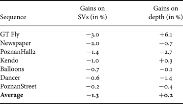
Table 4. Coding gains for the entire set of frames in SVs and depth with GradientMax.

C) Results analysis and conclusion
Our tool with the GradientMax criterion gives overall −1.3% gain on SVs, and minor losses (0.2%) on depth videos. The loss on depth videos can be explained by the fact that the RDO process in HTM-0.3 optimizes depth map coding for the quality of the SVs (due to VSO). This means that a coding mode that is optimal for a currently coded depth PU may not be selected for this PU if it is not optimal for synthesis. Since our tool introduces a new predictor for depth Intra modes, the RD choices are altered and this may lead in some cases, as in the GT Fly sequence, to a selection of Intra modes that improves significantly the quality of the synthesis (−3.0% gain) at the expense of an even bigger loss on depth (6.1%). Consequently, the gains on depth are not very relevant here.
The gains on SVs for the entire set of frames are lower than if they are evaluated only the first frame. This is due to the fact that the threshold is not optimized per frame, but only on the first frame of the sequences. Our optimization process to obtain the threshold can however be done online, using a multi-pass encoder which codes the frame N times until it finds the threshold giving the largest gains, and then finally codes the frame using the threshold obtained. This also means that the encoder should transmit the threshold to the decoder for each frame. Nevertheless, the results given would still hold because the extra signaling is minimal. If this has to be done for each frame, the whole encoding process would turn out to be very complex. Optimizing on the first frame, as we have presented it, can therefore be seen as a compromise between coding efficiency and complexity.
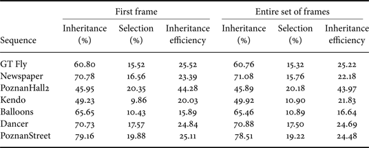
The inheritance and selection percentages, and the inheritance efficiency of our method for both test cases and for each sequence are given in Table 5. The inheritance percentage is the ratio between the number of PUs where a texture Intra mode inheritance occurs and the total number of coded PUs. The selection percentage is the ratio between the number of PUs where a texture Intra mode inheritance occurs and where this inherited mode turns out to be the best (RD wise) mode for the PU (so in other words, the number of PUs where we “correctly” inherit) and the total number of coded PUs. The inheritance efficiency is the ratio between the selection and the inheritance percentages. We can see that the depth and SVs gains are correlated with the selection percentages shown in Table 5. Of course, this is not an exact measure, since inheriting the texture Intra mode and selecting it as the best (RD) mode for a PU does not necessarily imply gains (the mode in question might already be in the MPM list as a spatial candidate). Likewise, inheriting the texture Intra mode and not selecting it as best R-D mode does not necessarily imply losses (the texture Intra mode would have to replace a predictor which would have been selected as best RD mode, or get inserted next to it hence increasing its signaling bitrate in case it was alone in the list). Nevertheless, the selection percentage still gives us an idea on the performance of the tool in the various tested sequences. In general, as it increases, the gains (considered on both the depth and SVs) increase also.
Table 5. Inheritance and selection percentages, and inheritance efficiency with GradientMax.
We believe that the coding gains could be higher, if a better texture mode inheritance criterion is considered, even at the cost of a slightly higher computational cost. The work devoted to finding and testing this criterion is presented in the next section.
V. THE DOMINANTANGL CRITERION
A) Preliminary Study
An analysis of the texture–depth Intra modes matchings shows that they mostly occur in PUs where there is only one sharp directional edge in texture rather than in PUs that have several edges in texture, or one edge which does not have a dominant direction.
Figure 6 shows two texture CUs, one having a sharp edge which does not have a single dominant direction, and another having a single sharp directional edge. The first CU (Fig. 6(a)) is likely to be partitioned in the texture encoding pass because it is difficult to find an Intra mode which gives an acceptable prediction of the texture signal. Hence, there will not only be one Intra mode for this CU, but rather one for each partition. Inheriting one of these Intra modes (in practice, it is the one of the top left PU which will be inherited, as shown in Fig. 4) for the co-located depth PU is not efficient because the inherited Intra mode is not pertinent in depth. In these situations, it is better not to inherit at all. In the second PU however (Fig. 6(b)), a specific Intra mode is able to perfectly describe the dynamics of the PU (hence giving a good prediction signal) and will thus be retained for coding the texture PU. This mode is also able to describe accurately the dynamics of the co-located depth PU and hence, in this case, it is efficient to inherit it.
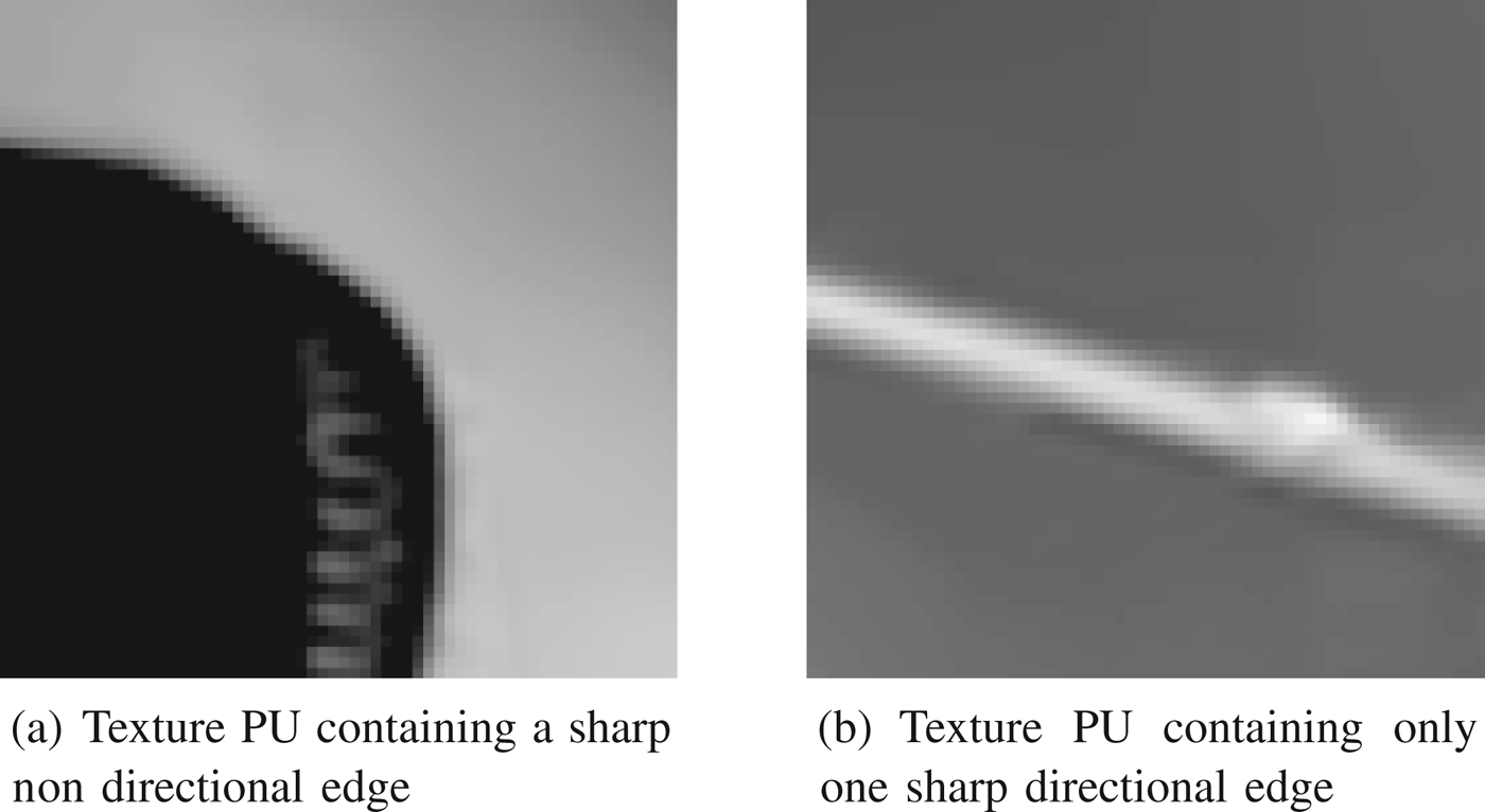
Fig. 6. Two types of texture PUs containing sharp edges.
Figure 7 shows the module of the gradient computed as in equation (1) for the two PUs of Fig. 6. The red pixels in the module matrices correspond to sharp edges. The maximum value of the module matrix in the first case equals 346 and in the second case, it equals 337. These are the values of the GradientMax criterion if used. Both are relatively high values. Indeed, if the threshold is set to 50 as in the previous case, the texture Intra mode will be inherited in both cases since both metrics are larger than 50. This inheritance is fine for the second case, but not for the first case. Consequently, there is a need to develop a new criterion which accounts for the direction of the edge and not only its sharpness.

Fig. 7. Module matrices obtained after Sobel filtering of two types of texture PUs containing sharp edges.
B) Proposed criterion
We have developed a new criterion, DominantAngle, that takes into account the direction of the edges present in the texture PUs.
To compute the metric associated with the criterion, we first perform a gradient calculation on the texture PU. Besides the gradient module, we also compute its angles A as follows:
The module matrix shows the magnitude of the edges in the texture PU. The angles matrix gives the direction of these edges. For the computation of the metric, we establish the histogram of these angles, but only the angles corresponding to edges with a relatively high module value (50 in our method, as in GradientMax) are considered. The histogram will thus list the number of occurences of the angles corresponding only to sharp edges. To establish the histogram, a number of bins has to be set. We choose β = 33 bins which correspond to the number of directional Intra modes in HEVC.
The aim is to find PUs containing a single sharp directional edge. Thus, we have to detect a single peak (local maximum) in the histogram, corresponding to that edge. Having other distant peaks in the histogram discredits the initial peak and decreases the pertinence of the texture mode to be inherited. Consequently, we propose to compute the metric as follows:
-
(1) First, initialize the metric c to the maximum histogram value (highest peak). Let x c denote the bin index of that value in the histogram.
-
(2) If c = 0, stop the algorithm. Else, find the next highest value in the histogram, denoted as p, with a bin index of x p
If $p \ge \alpha \ast c$
, reduce c such that:
(3)and return to Step 2.
 $$c \leftarrow c \ast \left(1 - \displaystyle{{\vert {x_c} - {x_p}\vert } \over \beta } \right).$$
Else, stop the algorithm.
This criterion penalizes the maximum histogram value if there are other peaks in the histogram and that penalty is proportional to the distance separating the two peaks, which corresponds to the angle difference. The binning operation, which can be seen as a type of quantization, may lead to the insertion of two close angles into seperate bins. Thus, we can find in some cases two high histogram values that are next to each other. These are not two different peaks. The criterion initialized to the highest value should not be penalized by the presence of the other, because it is practically the same angle, the difference being only due to the binning operation. Equation (3) accounts for this situation. Furthermore, the α parameter is optimized and empirically set to 0.75 for maximum coding gains.
Figure 8 shows the angle histograms of the two PUs in Fig. 6. For the PU which contains a sharp non-directional edge, the histogram presents many peaks while the histogram of the PU containing only one sharp directional edge contains only one peak that corresponds to that direction. The above-mentionned metric computation gives the values of 4 and 344, respectively. If the threshold is set to 50, this means that we will inherit only in the second case and not in the first case, and that is exactly what is required.

Fig. 8. Angles histograms of two types of texture PUs containing sharp edges.
As opposed to the GradientMax criterion case, the threshold used for the DominantAngle criterion is PU size dependent since the maximum number of occurences of an angle in the histogram of an N × N PU equals N Reference Rusanovsky, Chen, Zhang and Suzuki 2 . Each PU size has a different criterion dynamic. If the computed metric in a PU of a given size is larger than the threshold corresponding to that PU size, the texture Intra mode is inherited and is inserted into the MPM candidate list. Experiments show that normalizing the computed metric by N Reference Rusanovsky, Chen, Zhang and Suzuki 2 to obtain a single threshold for all PU sizes is not the most efficient solution, as bigger PU sizes have a higher weight than smaller ones, and thus require a higher threshold.
VI. EXPERIMENTAL RESULTS WITH THE DOMINANTANGLE CRITERION
A) Experimental setting
We implement DominantAngle in the same experimental framework and testing conditions as the GradientMax criterion (see Section IV-A) to allow for a fair comparison between the two.
The threshold for each PU size is empirically determined. These thresholds are fixed and are known by both the encoder and decoder so they do not need to be transmitted. In HTM-0.3, PU sizes vary from 64 × 64 to 4 × 4. Hence, there are five different PU sizes, and five different thresholds to determine. Here also, the optimization is done only on the first frame and the best thresholds obtained are used to code the rest of the frames. Indeed, the optimization process here is even more complex than in GradientMax since it has to be done independantly for each PU size. Thus, in this section, we also present coding gains on the first frame, and on the entire set of frames.
The optimization process consists of an exhaustive search for the best threshold for each PU size, starting with 64 × 64. All the other thresholds are set to 0. Once the threshold that maximizes the average view synthesis gain for all sequences is found, another exhaustive search is performed for 32 × 32 PUs. The threshold for the 64 × 64 PU size is set to the previously found threshold and all the others are set to 0. This process is repeated until all five thresholds were found. The optimal thresholds found after exhaustive searches are 15 for the 64 × 64 PUs and 0 for smaller PU sizes.
B) Coding gains
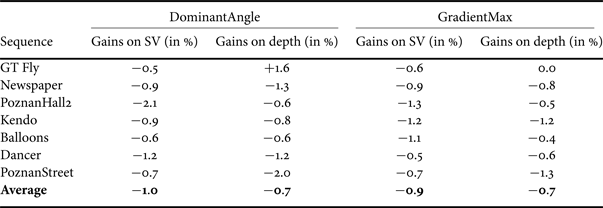
Table 6 shows the coding gains, evaluated on SV and on coded depth views, for the first frame of each sequence in the test set, on which the threshold optimization is performed. Average bitrate reductions of 1.6 and 2.3% are reported for SV and depth videos, respectively. Gains for the entire set of frames are given in Table 7. In this scenario, average bitrate reductions equal 1.0 and 0.7%, respectively. These two tables also recall the gains of GradientMax for comparison.
Table 6. Coding gains for the first frame on SVs and depth with DominantAngle and GradientMax (for comparison).
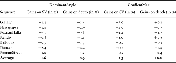
Table 7. Coding gains for the entire set of frames on SVs and depth with DominantAngle and GradientMax (for comparison).
C) Results Interpretation
The optimal thresholds obtained imply that in PUs smaller than 64 × 64, we always inherit the texture Intra mode. In these PUs, the gains obtained by exploiting all possible matchings overcome the loss induced by the occasional replacement of a good spatial predictor with the inherited texture Intra mode. For 64 × 64 PUs, this is not the case. A threshold must be established to avoid inheriting in patterned PUs in texture or at edges intersections, since those PUs contain many directional contours. Furthermore, the weight of a 64 × 64 PU is significant. A bad prediction in this PU affects the prediction and coding of many subsequent PUs. Hence, for this PU size, the optimal threshold is 15.
Furthermore, the inheritance and selection percentages, and the inheritance efficiency of our method for both test cases and for each sequence are given in Table 8. The gains shown in Tables 6 and 7 are correlated with these selection percentages. In most cases, when the selection percentage increases, the gains increase as well. Compared to GradientMax (see Table 5), DominantAngle yields more frequent selections, but more frequent inheritances as well. This is due to the fact that the threshold for PU sizes different than 64 × 64 is 0, meaning the texture Intra mode is always inherited in those PUs.
Table 8. Inheritance and selection percentages and inheritance efficiency with DominantAngle.

Figure 9(c) shows, in yellow, the PUs in which a texture–depth Intra mode matching can be exploited in the first frame of the central view of the PoznanHall2 sequence. Figure 9(d) shows, in green, the PUs where the texture Intra mode is inherited using GradientMax, and Fig. 9(e) shows the same with DominantAngle. We can see that there are more green PUs in DominantAngle than in GradientMax. DominantAngle covers more yellow PUs than GradientMax (hence the observed increase in the selection percentages), but also more PUs where there is not a matching to exploit, and those are mostly smaller size PUs due to the threshold set to 0 for these PU sizes.

Fig. 9. Texture–depth Intra mode matchings PUs and inheritance PUs with the GradientMax and DominantAngle criteria, in the first frame of the central view of PoznanHall2.
However, that increase in the inheritance percentage in DominantAngle, and consequently, in the percentage of PUs where the texture Intra mode is inherited but not selected (which can be seen as the difference between the inheritance and the selection percentage), is not problematic. As previously said, the fact that the texture Intra mode is inherited for a PU and not selected does not always imply losses. But even if it does, the losses would be minimal because they occur in smaller PU sizes. Also, the smaller the PU size, the more planar the depth PU and the corresponding texture PU would be, and, in these cases, the best mode is most probably either the non-directional Planar or DC mode. Inheriting one instead of the other is certainly not ideal, but is not catastrophic either as both succeed in representing the dynamics of a planar PU.
There are however some PUs where an inheritance can happen in GradientMax, and not in DominantAngle, and those are PUs where there is more than one sharp directional edge in texture. Avoiding to inherit in these PUs will reduce losses in DominantAngle compared to GradientMax. Figure 9(c) shows for instance that there is no Intra mode matching in the first 64 × 64 top-left PU in the depth map of the central view of PoznanHall2. This is expected, because the corresponding texture PU is actually patterned, as shown in Fig. 10, so it has no pertinent Intra mode to offer for its corresponding depth PU. In GradientMax, an inheritance is made in this case, as shown in Fig. 9(d), but that is successfully avoided in DominantAngle, as shown in Fig. 9(e).

Fig. 10. First top-left 64 × 64 PU (with adjusted contrast for visibility) of the first texture frame in the central view of PoznanHall2.
When comparing the stability of the optimal threshold obtained for each criterion (for DominantAngle it is the 64 × 64 threshold) as shown in Fig. 11, we find that in the case of DominantAngle, when the threshold approaches the optimal value (15), the coding gain varies very quickly. However, we also observe that, even if we make a wrong guess about the best value (for example we double the value and use 30), the gain are still high (−1%). Even if we use an overestimated value (e.g. 120, 8 times the best value), we still keep half of the gains. In conclusion, it is important to use the best threshold value, but globally this technique is robust with respect to the selection of this parameter.

Fig. 11. Average gains on SV as a function of the threshold.
As far as the GradientMax method is concerned, we observe a similar behavior. The best value of the threshold is 50, which gives 1.3% rate reduction. If this value is halved, we still have 0.9% rate reduction. On the other hand, when the threshold is doubled we only gain −0.3%, and when it is quadrupled, all the gains are lost. We conclude that the GradientMax method, not only has a smaller best gain, but is also a bit less robust with respect to the threshold selection.
When further analyzing the gains we obtain on SV for each proposed criterion, considering the more realistic scenario where we code all the frames, we can see (from Table 7) that the results are somewhat coherent across sequences. The standard deviation equals 0.50 for DominantAngle and 0.29 for GradientMax which are relatively small values. For DominantAngle, the gains vary between 50 and 210% of the average gain value whereas in GradientMax the gains vary between 56 and 144%. We believe that these ranges are acceptable. Both methods are statistically stable in that sense, and even though GradientMax outperforms DominantAngle in some sequences, on average, DominantAngle is better. Consequently, we have succeeded in finding a better criterion than GradientMax.
VII. CONCLUSION
In this work, we have presented a novel depth video coding tool that exploits the statistical dependency between the texture and depth Intra modes in order to increase the coding efficiency and achieve gains on SV. The proposed method first finds the corresponding texture PU for a currently coded depth PU. Then it computes a metric on that texture PU and if it is larger than a specified threshold, adds the texture Intra mode to the MPM candidate list where it may replace another spatial candidate.
Two criteria were studied in this work: GradientMax and DominantAngle. The rationale behind the GradientMax criterion is that the texture–depth Intra mode matchings occur only in areas where there are sharp edges in texture. Based on that assumption, the metric was set as the sharpness of the edges present in the texture PU. Our tool associated with the GradientMax criterion gave −1.3% gain on average for synthesized sequences and a small loss on depth, when the corresponding threshold was optimized. A further study showed that our initial assumption was not completely accurate. Texture–depth Intra mode matchings actually occured in areas where there is one sharp edge in texture. This meant that the initial inheritance set was actually a superset of the appropriate inheritance set. Based on this remark, we developed a new criterion, DominantAngle, which accounted for the direction of the edge in a texture PU. This new criterion gave −2.3% gain on depth sequences and −1.6% gain on synthesized sequences with optimized thresholds.
In the future, we will implement a more intelligent content-adaptive and systematic way to drive the inheritance without relying on complex threshold optimizations. Furthermore, the direct inheritance of the texture Intra mode can also be considered (wherein the currently coded depth PU is forced to be coded with the inherited mode, without having to signal this mode in the bitstream since the same process can be repeated at the decoder) if the statistical dependency is expected to be exceptionally high. The resulting progressive inheritance scheme would therefore be able to adapt itself to the degree of dependency between texture and depth Intra modes in order to increase coding efficiency.
ACKNOWLEDGEMENT
The authors acknowledge the support of the Persee project (ANR-09-BLAN-0170).


