

I. INTRODUCTION
The parametric array loudspeaker (PAL) is an application of the parametric acoustic array in air [Reference Bennett and Blackstock1]. It was discovered by Westervelt in the early 1960s that two collimated high-frequency beams could result in the generation of a low-frequency sound beam as a result of nonlinear acoustic effects [Reference Westervelt2]. The high-frequency components were commonly referred to as the primary frequency and the low-frequency component generated from the interaction of primary frequencies was thus referred to as the difference frequency. After Westervelt published his discovery of the parametric acoustic array, Berktay studied a self-demodulation phenomenon caused by the same nonlinear acoustic effects. Berktay found out that when an acoustic wave was transmitted in the form of a pulsed carrier, it was self-demodulated to its envelope, which consisted of much lower frequency components than the carrier frequency, after a sufficiently large propagation distance [Reference Berktay3]. This was known as the Berktay's far-field solution. Therefore, the sound principle of the PAL happens when a modulated ultrasonic carrier is transmitted into air. The modulating sound is cumulatively formed in the beam of the ultrasonic carrier as described by the Berktay's far-field solution, and it will continue to propagate beyond the absorption distance where the ultrasonic carrier has been sufficiently attenuated [Reference Shi and Gan4].
Signal processing is of critical importance in the development of the PAL. Nonlinear distortions have been the top technical barrier to promote the use of the PAL. Ever since the PAL was invented [Reference Yoneyama, Fujimoto, Kawamo and Sasabe5], a variety of signal processing methods have been proposed to address nonlinear distortions in the PAL. Kamakura et al. have suggested that the square-root operation preprocess the envelope of the double sideband modulation method, which can substantially reduce the second harmonic distortion [Reference Kamakura, Yoneyama and Ikegaya6]. Kite et al. have further added the double integral operation in front of the square-root operation to treat the higher order harmonic distortions [Reference Kite, Post and Hamilton7]. After that, the single sideband modulation method was introduced to fully eliminate harmonic distortions based on the Berktay's far-field solution. However, the practical performance of the single sideband modulation method was not as good as the double sideband modulation method. It was because that when pressure levels of primary frequencies were high, the Berktay's far-field solution was no longer valid [Reference Aoki, Kamakura and Kumamoto8]. Recently, there were many new methods applied in the PAL, such as the quadrature modulation method [Reference Liew9], recursive modulation method [Reference Croft, Spencer and Norris10], and hybrid modulation method [Reference Shi and Gan11]. All of these methods were highly optimized to a specific acoustic model. They encountered the same limitation as the single sideband modulation method that discrepancies between the applied environment and acoustic model assumptions led to significant performance degradation. Therefore a superior method to address nonlinear distortions of the PAL should be able to adapt to the applied environment. One such solution is the nonlinear system identification of the PAL using a Volterra series [Reference Ji and Gan12–Reference Mu, Ji, Ji, Wu and Yang14]. On the other hand, a psychoacoustical method has been tested in the PAL to generate the virtual bass effect by equalizing the residual harmonic distortions that cannot be completely eliminated at this stage [Reference Shi, Mu and Gan15].
There are various studies that use the PAL as an accessible compact directional source. Sound field control is one of them targeting at tailored enhancement and attenuation of acoustic components [Reference Elliot16]. The PAL has been employed in sound field control applications, such as the audio projection [Reference Aoki, Toba and Tsujita17], three-dimensional sound reproduction [Reference Shi, Nomura, Kamakura and Gan18], immersive communication [Reference Gan, Tan and Kuo19], and active noise control (ANC) [Reference Lam, Gan and Shi20]. The computational complexity of a multi-channel ANC system using PALs as secondary sources is greatly reduced, because crosstalk secondary path models can be removed [Reference Tanaka, Shi and Kajikawa21, Reference Tanaka, Shi and Kajikawa22]. Being relatively small in size, the PAL has substituted conventional miniature loudspeakers in the mobile phone [Reference Nakashima, Yoshimura, Naka and Ohya23] and interactive humanoid [Reference Nakadai and Tsujino24]. The PAL has also been employed in nondestructive testing, such as the landmine detection [Reference Haupt and Rolt25], weapon detection [Reference Achanta, McKenna and Heyman26], material measurement [Reference Kuang, Ye, Wu and Yang27], and art preservation [Reference Calicchia, Simone, Marcoberardino and Marchal28].
Although a controllable sound beam enhances the ease of using the PAL in different applications, there has been only a limited number of studies to control the directivity of the PAL. The emitter of the PAL consists of numerous ultrasonic transducers. In the past studies, addressing nonlinear distortions of the PAL, the emitter of the PAL was considered as an ultrasonic source en bloc. However, when phased array techniques are applied to control the directivity of the PAL, ultrasonic transducers in the emitter of the PAL have to be configured into multiple channels, which are driven individually. This configuration can be interpreted as an array of PALs because every channel consists of a number of ultrasonic transducers and operates as a PAL. The delay-and-sum beamformer has been proved effective in controlling the directivity of the PAL, but other sophisticated methods are usually not applicable due to lack of an accurate directivity model of the PAL with a low computational complexity [Reference Shi29].
The rest of this paper is organized as follows. Directivity control methods of the PAL are elaborated in Section II. The product directivity principle and past studies to improve the accuracy of the product directivity principle are presented in Section III(A). One of the latest directivity models of the PAL, namely the convolution model, is provided in Section III(B). One advantage of the convolution model is that environmental conditions, such as the room temperature and relative humidity, are taken into account. Using the convolution model, the beamwidth of the PAL is shown under different environmental conditions in Section IV(A). The constant beamwidth beamformer and digital beamsteerer of the PAL are described in Sections IV(B) and IV(C). In addition, the digital beamsteerer of the PAL is examined when spatial aliasing at the primary frequency occurs. Lastly, Section V concludes this paper and charts new research directions of the PAL.
II. DIRECTIVITY CONTROL METHOD OF THE PAL
There are two types of directivity control methods of the PAL. They are the mechanical and signal processing methods. The mechanical method is built with motorized rotation stages and reflective objects, whereas the signal processing method is implemented in analog circuits and digital processors. The disadvantage of the mechanical method owes to its overall size and additional reflections caused by the motorized rotation stages and the reflective objects.
A) Mechanical method
The PAL is commonly used in the direct mode to project a sound beam to a listener. However, there is another reflected mode of the PAL. A virtual sound source is formed at the point of reflection when the PAL is placed to face a reflective surface as shown in Fig. 1. The PAL operating in the reflected mode has been employed in an ANC system [Reference Tachi and Tanaka30], where the secondary source was invisible to the control point. Changes to the reflective surface can lead to certain directivity control of the PAL. The quadrilateral reflector diverts the beam direction of the PAL and the hemispherical reflector widens the beamwidth of the PAL [Reference Morise, Ikefuji, Tujii, Hirokawa and Nishiura31]. Olszewski and Linhard [Reference Olszewski and Linhard32] have reported that the presence of a listener's head in the near field of the PAL results in a diffused sound field. This observation can be explained by the similarity in shape between the listener's head and hemispherical reflector.
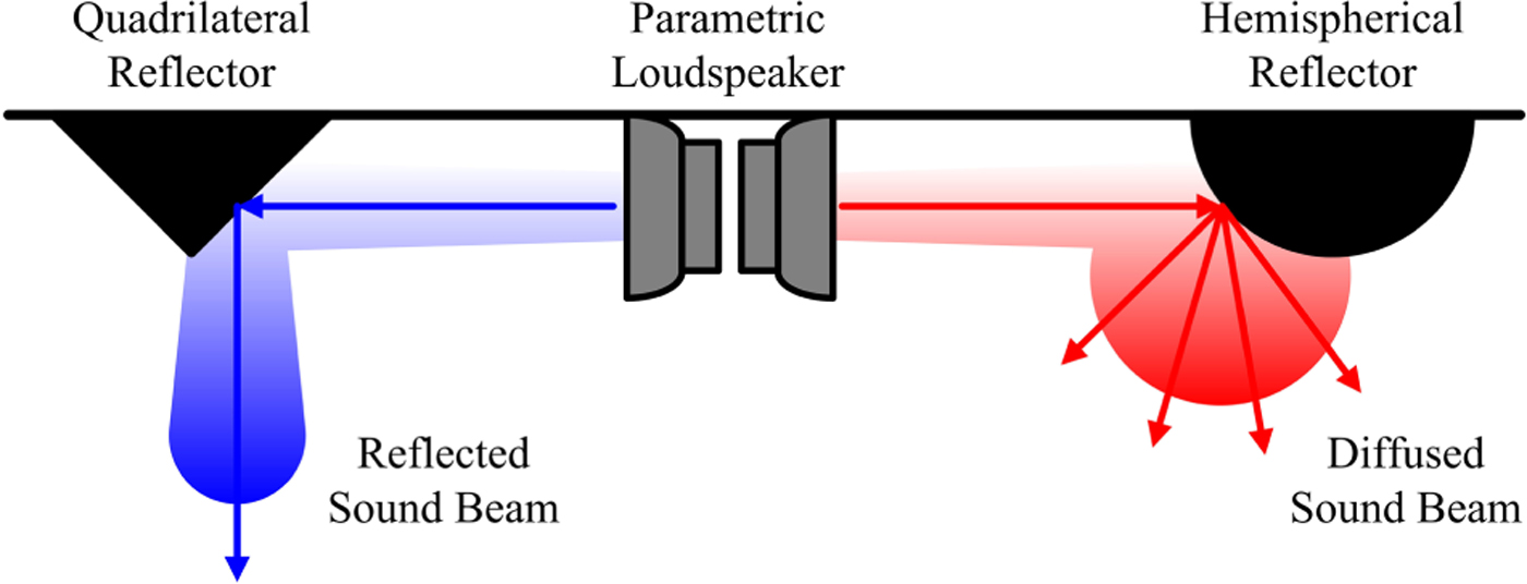
Fig. 1. Sketches of the quadrilateral and hemispherical reflectors for controlling the directivity of the PAL.
A motorized rotation stage can easily change the beam direction of the PAL. Ishii et al. [Reference Ishii, Yamamoto, Imai and Nakadai33] developed an indoor navigation system, in which the PAL was installed on a motorized rotation stage to send private messages to a moving listener. A similar setup is often adopted in the directivity measurement of the PAL. As illustrated in Fig. 2, the PAL is fastened on a motorized rotation stage and a microphone is placed in the far field of the PAL. Sound absorbing treatments to the walls of the measurement room are highly recommended. Moreover, an array of PALs can be tilted simultaneously by many motorized rotation stages. A prototype of one such motorized PAL array was built by Olszewski et al. [Reference Olszewski, Prasetyo and Linhard34], which consisted of four PALs tilting in unison. In this motorized PAL array, digital delays were also implemented in all the four channels to compensate for phase deviations among the PALs.
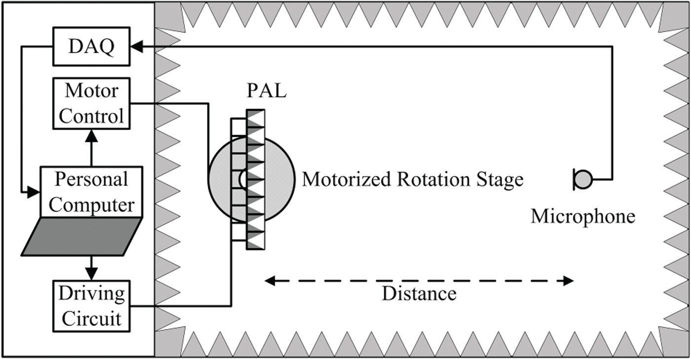
Fig. 2. Directivity measurement setup of the PAL.
B) Array configuration
Array configuration is another important aspect of the directivity control of the PAL. Olszewski and Linhard [Reference Olszewski and Linhard35] compared different configurations of the PAL and recommended a ring configuration that could narrow the beamwidth of the PAL over the low-frequency range. Figure 3(a) shows the front view of the ring configuration. Besides, a dedicated uneven surface as shown in Fig. 3(b) compensated for phase deviations among ultrasonic transducers [Reference Olszewski, Prasetyo and Linhard34]. A curved PAL mimicking the concave lens as shown in Fig. 3(c) was used in global ANC [Reference Tanaka and Tanaka36]. The focus point of the concave PAL was configured at the noise source to create an exact anti-noise source to reduce the noise level globally. In the three-dimensional sound reproduction, a convex PAL as shown in Fig. 3(d) outperformed the concave PAL in terms of the size of the sweet spot [Reference Ikefuji, Tsuji, Masnaga, Nakayama, Nishiura and Yamashita37]. Besides changing the array configuration of the PAL, the directivity of the PAL was also narrowed when a horn was attached to the PAL, which was shown in Fig. 3(e) [Reference Sayin and Guasch38].
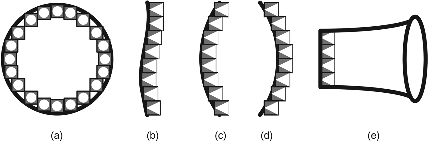
Fig. 3. Various array configurations of the PAL.
An array of PALs was used as a multi-beam PAL and was mounted on the ceiling of a conference room to form a corresponding number of personal audio zones simultaneously [Reference Olszewski and Linhard39]. As compared to the loudspeaker array, the power consumption and control complexity of this multi-beam PAL were reduced significantly. In a mixed reality system, an icosahedral PAL transmitting 10 sound beams were employed to create virtual sound sources to provide a user with immersive listening experience [Reference Sugibayashi, Kurimoto, Ikefuji, Morise and Nishiura40]. The icosahedral PAL outperformed small-scale loudspeaker systems in terms of its localization accuracy, because the sound field reproduced by the icosahedral PAL was independent from individual head-related transfer functions.
In the acoustic measurement of a reverberant environment, a diffused acoustic source is essential but very expensive. An omnidirectional PAL was implemented by pinning hundreds of ultrasonic transducers on hollow sphere foam [Reference Sayin, Artis and Guasch41]. This omnidirectional PAL became a budget substitute to the expensive dodecahedron loudspeaker and demonstrated a more stable omnidirectional pattern over a wide frequency range. The low-frequency sound level of this omnidirectional PAL was relatively soft, which was another recognized drawback of the PAL [Reference Shi, Mu and Gan15].
C) Array signal processing
Figure 4 shows a delay-and-sum beamforming structure of the steerable PAL [Reference Shi and Gan42]. The weight for the mth channel is denoted as w m , where m = 0, 1, 2, …, M − 1 and M is the number of channels in the steerable PAL. Usually, the same delays are applied to all primary frequencies in every channel, which are given by
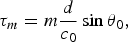 $$\tau_m = m \displaystyle{{d}\over{c_0}} \sin \theta_0\comma \;$$
where d is the uniform spacing between neighboring channels; c 0 is the speed of sound; θ0 is the steering angle [Reference Shi and Gan43]. When the wavefront of the primary frequency is formed in one direction, the difference frequency generated from the interaction of primary frequencies is strengthened in the same direction. The quantitative description of this statement is called the product directivity principle, which is elaborated in the next section.
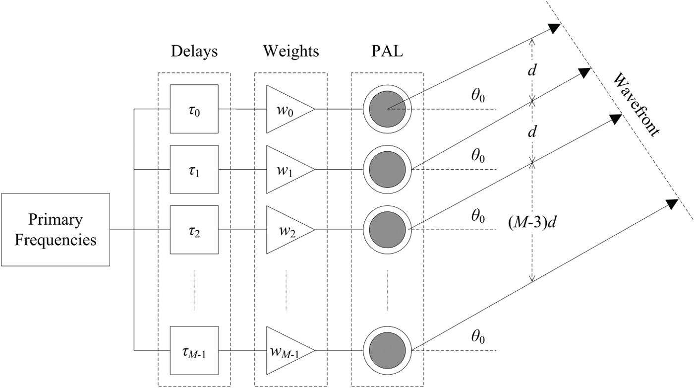
Fig. 4. Delay-and-sum beamforming structure of the steerable PAL.
The effectiveness of the steerable PAL was validated in an application of ANC [Reference Tanaka and Tanaka44]. It was noted that when the PAL was used as the secondary source, not only was the noise level at the control point reduced, spillovers of the anti-noise wave to other areas were also restricted. Moreover, the steerable PAL enabled the relocation of the control point to follow a moving listener. In a field programmable gate array (FPGA) implementation of the steerable PAL [Reference Wu, Wu, Huang and Yang45], fractional delay filters provided arbitrary delays for the primary frequency and consequently improved the angular resolution that was limited by the sampling interval. Instead, another FPGA implementation of the steerable PAL had to adopt a sampling rate at 1.4 MHz to yield an angular resolution of 2° [Reference Takeoka and Yamasaki46]. A remarkable advantage of the steerable PAL in [Reference Takeoka and Yamasaki46] was that it consisted of 576 channels and could transmit multiple controllable sound beams simultaneously.
The steerable PAL is gaining attention in assistive hearing too. For example, an elderly person with a hearing loss is watching a television program together with other people with no hearing loss. The steerable PAL can supplement the television loudspeaker system to enhance the listening experience of the elderly person with a hearing loss and prevent the excessive sound from spreading to the other people [Reference Shi47]. Furthermore, an array of PALs can reproduce an arbitrary wavefront with the help of wave field synthesis (WFS) techniques. A global quiet zone can be created regardless of the listener's position when virtual anti-noise sources are created in the vicinity of all actual noise sources [Reference Ishimori, Tanaka and Iwamoto48].
III. DIRECTIVITY MODEL OF THE PAL
In this section, directivity models of the PAL are elaborated. The directivity of the PAL plays an important role in various applications of the PAL. Although there have been many nonlinear acoustic models describing the sound principle of the PAL, they seldom address the directivity of the PAL. The most widely used nonlinear acoustic models including the Westervelt and Khokhlov–Zabolotskaya–Kuznetsov (KZK) equations [Reference Westervelt2–Reference Shi and Gan4] have no general analytical solution. Numerical solutions are only available with a heavy computational load, especially when the directivity of the PAL is computed over a wide angle range. Therefore, it has been a long existing problem to accurately compute the directivity of the PAL with a low computational complexity when directivities of primary frequencies are given.
A) Product directivity principle
Early attempts to model the directivity of the PAL were carried out on the basis of the product directivity principle [Reference Gan, Yang, Tan and Er49]. If the emitter of the PAL was a Gaussian source en bloc, the product directivity of two primary frequencies was able to approximate the directivity of the difference frequency. The product directivity principle is easily applied in the development of the steerable PAL. However, since assumptions of Gaussian source are partially ignored, the accuracy of the product directivity principle is not satisfactory.
To improve the accuracy of the product directivity principle, Shi and Gan [Reference Shi and Gan50] have introduced the equivalent Gaussian source array. In the equivalent Gaussian source array, the directivity of every Gaussian source approximates a lobe in the directivity of a primary frequency. Coefficients of the equivalent Gaussian the source array are determined by the nonlinear regression analysis based on the following model:
 $$D\lpar \theta\rpar = \sum_{n=1}^N p_n \exp \left[-\left(\displaystyle{{\omega a_n}\over{2c_0}}\right)^2 \tan^2 \lpar \theta - \theta_n\rpar \right]\comma \;$$
where θ is the independent variable; ω is the primary frequency; N is the number of Gaussian sources; p n , a n , and θ n are the amplitude, radius, and steering angle of the nth Gaussian source, respectively. Measured directivities of the primary frequency provide the observational data in the nonlinear regression analysis. The use of the equivalent Gaussian source array allows assumptions of the Gaussian source to be valid in the PAL.
Based on the equivalent Gaussian source array, three modifications to the product directivity principle have been derived. They are the advanced product directivity (APD), exponential product directivity (EPD), and combined product directivity (CPD) models [Reference Shi and Gan51]. Taking the APD model into account, the directivity of the difference frequency is computed by
 $$\eqalign{D_d \lpar \theta\rpar &= \sum_{m = 1}^{N_1} \sum_{n = 1}^{N_2} \left\{\displaystyle{p_{1\comma m} p_{2\comma n} a_{1\comma m}^2 a_{2\comma n}^2\over{a_{1\comma m}^2 + a_{2\comma n}^2}} \right. \cr & \quad \left. \times \exp \left[\displaystyle{\matrix{{-a_{1\comma m}^2 \omega_1^2 \tan^2 \lpar \theta - \theta_{1\comma m}\rpar } \cr - {a_{2\comma n}^2 \omega_2^2 \tan^2 \lpar \theta - \theta_{2\comma n}\rpar }} \over {4c_0^2}}\right]\right\}.}$$
In equation (3), N 1 and N 2 are numbers of Gaussian sources of the two primary frequencies, respectively. The product directivity principle is applied to every pair of Gaussian sources in the equivalent Gaussian source array. Superposition of all the product directivities yields the directivity of the difference frequency. In the experiment validation in [Reference Shi and Gan51], the APD model has demonstrated a higher accuracy as compared to the product directivity principle, and the EPD and CPD models have shown similar accuracies but with higher computational complexities as compared to the APD model.
So far, there are two remaining drawbacks of the product directivity principle and models. Firstly, the beamwidth of the PAL is wider in practice than model results. Secondly, sidelobes of the PAL are observed in model results but are rarely found in practice. Therefore, a postprocessing method has been used for the product directivity principle and models. In this postprocessing method, the spline interpolation between local maxima of the model result leads to an improved match to the measured directivity of the difference frequency [Reference Shi and Gan52, Reference Shi, Nomura, Kamakura and Gan53]. Nevertheless, this postprocessing method lacks theoretical evidences.
B) Convolution model
Recently, a convolution model based on the Westervelt's directivity has been originated. The convolution model provides an accurate directivity model for the PAL. Derivation of the convolution model is presented in this subsection and three applications of the convolution model are provided in the Section IV.
Firstly, according to assumptions made by Westervelt [Reference Westervelt2], primary frequency beams are extremely narrow and perfectly collimated so that a one-dimensional equation is adequate to represent the source distribution. The complex form of the primary source pressure level is assumed as
 $$p\lpar x\comma \; t\rpar = \sum_{m=1}^2 P_m \exp \left[-\alpha_m x + i\omega_m \left(t - \displaystyle{{x}\over{c_0}}\right)\right]\comma \;$$
where P m and α m are the amplitude and attenuation rates of the mth primary frequency at ω m , respectively; and i is the imaginary unit.
The source strength density of the primary source is known as
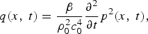 $$q\lpar x\comma \; t\rpar = \displaystyle{{\beta}\over{\rho_0^2 c_0^4}} \displaystyle{{\partial^2}\over{\partial t}}p^2 \lpar x\comma \; t\rpar \comma \;$$
where β is the nonlinear coefficient and ρ0 is the density of air. Hence, when equation (4) is inserted into equation (5), the source strength density of the difference frequency is obtained as
 $$\eqalign{q_d \lpar x\comma \; t\rpar &= \displaystyle{{\beta P_1 P_2}\over{\rho_0^2 c_0^4}}\lpar -i\omega_d\rpar \cr & \quad \times \exp \left[-\lpar \alpha_1 + \alpha_2\rpar x - i\omega_d \left(t - \displaystyle{{x}\over{c_0}}\right)\right]\comma \; }$$
where ω d is the difference frequency, much lower than primary frequencies.
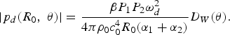
The geometry in Fig. 5 is applied to derive the Westervelt's directivity, which yields the pressure level of the difference frequency in the form of
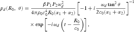 $$\eqalign{p_d \lpar R_0\comma \; \theta\rpar &= \displaystyle{{\beta P_1 P_2 \omega_d^2}\over{4\pi \rho_0 c_0^4 R_0 \lpar \alpha_1 + \alpha_2\rpar }} \left[-1 + i\displaystyle{{\omega_d \tan^2 \theta}\over{2c_0 \lpar \alpha_1 + \alpha_2\rpar }}\right]^{-1} \cr &\quad \times \exp \left[-i\omega_d \left(t - \displaystyle{{R_0}\over{c_0}}\right)\right]\comma \; }$$
where R
0 is the distance from the observation point to the PAL; and R is distance from the observation point to the virtual source located at x. The derivation of equation (7) follows the same steps of equation (12) in [Reference Westervelt2], but the approximation of
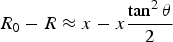 $R_{0} - R \approx x - x \displaystyle{{\tan^{2} \theta}\over{2}}$
is adopted here instead of the one of R
0 − R ≈ x cos θ used in [Reference Westervelt2]. Therefore, the Westervelt's directivity is given by the absolute value of the second term of equation (7), i.e.
$R_{0} - R \approx x - x \displaystyle{{\tan^{2} \theta}\over{2}}$
is adopted here instead of the one of R
0 − R ≈ x cos θ used in [Reference Westervelt2]. Therefore, the Westervelt's directivity is given by the absolute value of the second term of equation (7), i.e.
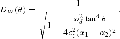 $$D_W \lpar \theta\rpar = \displaystyle{{1}\over{\sqrt{1 + \displaystyle{{\omega_d^2 \tan^4 \theta}\over{4c_0^2 \lpar \alpha_1 + \alpha_2\rpar ^2}}}}}.$$
Using the Westervelt's directivity in equation (8), the magnitude of equation (7) can be rewritten as
 $$\vert p_d \lpar R_0\comma \; \theta\rpar \vert = \displaystyle{{\beta P_1 P_2 \omega_d^2}\over{4 \pi \rho_0 c_0^4 R_0 \lpar \alpha_1 + \alpha_2\rpar }} D_W \lpar \theta\rpar .$$
When collimated primary frequency beams are transmitted at an angle of θ0, they can be expressed in directivities as
 $$D_1 \lpar \theta\rpar = P_1 \delta \lpar \theta - \theta_0\rpar \comma \;$$
and
 $$D_2 \lpar \theta\rpar = P_2 \delta \lpar \theta - \theta_0\rpar \comma \;$$
where δ (x) is the Kronecker delta function that gives 1 when x = 0 and 0 when x ≠ 0. Hence, the pressure level of the difference frequency is obtained by rotating the coordinate system of equation (9), i.e.
 $$\left\vert p_d \lpar R_0\comma \; \theta\rpar \right\vert = \displaystyle{{\beta D_1 \lpar \theta_0\rpar D_2 \lpar \theta_0\rpar \omega_d^2}\over{4\pi \rho_0 c_0^4 R_0 \lpar \alpha_1 + \alpha_2\rpar }} D_W \lpar \theta - \theta_0\rpar .$$
Under the assumption of the weak nonlinear interaction, the superposition principle of sound waves is still valid in the PAL. When a few pairs of collimated primary frequency beams are transmitted at different angles, the pressure level of the difference frequency is expressed by a summation as
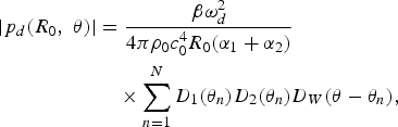 $$\eqalign{\left\vert p_d \lpar R_0\comma \; \theta\rpar \right\vert & = \displaystyle{{\beta \omega_d^2} \over {4\pi \rho_0 c_0^4 R_0 \lpar \alpha_1 + \alpha_2\rpar }} \cr &\quad \times \sum_{n = 1}^N D_1 \lpar \theta_n\rpar D_2 \lpar \theta_n\rpar D_W \lpar \theta - \theta_n\rpar \comma \; }$$
where D 1(θ n ) and D 2(θ n ) are equal to pressure levels of primary frequencies transmitted at the angle of θ n when n = 1, 2, …, N and N is the number of collimated beam pairs. In the directivity measurement, the directivity of a sound source is measured at a fixed distance from the source location and only at discrete angles. In this case, N becomes the number of angles where the directivity measurement is taken.
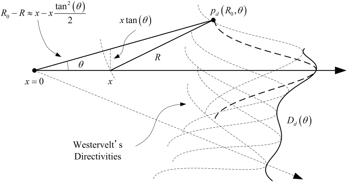
Fig. 5. Illustration of the Westervelt's directivity and convolution model of the PAL.
Based on equation (13), the directivity of the difference frequency is written as
 $$D_d \lpar \theta\rpar = \sum_{n=1}^N D_1 \lpar \theta_n\rpar D_2 \lpar \theta_n\rpar D_W \lpar \theta - \theta_n\rpar .$$
It is noted that equation (14) is in the form of a discrete convolution, which can be rewritten as
 $$D_d \lpar \theta \rpar = \lsqb D_1 \lpar \theta \rpar D_2 \lpar \theta \rpar \rsqb \otimes D_W \lpar \theta \rpar \comma \;$$
where ⊗ denotes the discrete convolution operation. In addition, when the PAL adopts the beamforming structure shown in Fig. 4, theoretical directivities of primary frequencies are computed by
 $$D_{1\comma 2} \lpar \theta\rpar = \left\vert \sum_{m = 1}^M \bar{w}_m \exp \left[i \displaystyle{w_{1\comma 2} \over {c_0}} {\it md}\lpar \sin \theta - \sin \theta_0\rpar \right]\right\vert\comma \;$$
where
 $\bar{w}_{m} = \displaystyle{w_{m} \over \sum_{m = 1}^{M} \vert w_{m}\vert\vert}$
is the normalized weight for the mth channel.
$\bar{w}_{m} = \displaystyle{w_{m} \over \sum_{m = 1}^{M} \vert w_{m}\vert\vert}$
is the normalized weight for the mth channel.
In equation (15), the convolution of the product directivity with the Westervelt's directivity yields the directivity of the difference frequency. Thus, it is named as the convolution model. Shi and Kajikawa [Reference Shi and Kajikawa54] have reported some experiment validations of the convolution model. Here another experiment validation is presented. A picture of the PAL consisting of 8 channels is shown in Fig. 6. When the steering angle is set to 0°, all the channels of this PAL are driven by the same modulated carrier. The full-width at half maximum (FWHM) of the beam is measured in directivities of the difference frequency at 1, 2, 4, and 8 kHz. Measurement results are compared with the model results of the product directivity principle, Westervelt's directivity, and convolution model. Figure 6 shows that the convolution model has demonstrated the closest match to measurement results.

Fig. 6. An experimental validation of the convolution model.
IV. DIRECTIVITY DESIGN OF THE PAL
The convolution model in equation (15) has opened an opportunity to directivity control methods of the PAL. In the past studies, there have been some attempts to apply sophisticated array signal processing methods in the PAL [Reference Gan, Yang, Tan and Er49, Reference Yang, Gan, Tan and Er55]. But they have been hindered owing to lack of an effective directivity model. Using the convolution model, we are able to study directivity control methods that were difficult to investigate. Therefore, three applications of the convolution model in the PAL are elaborated in this section.
A) Environmental influences on the FWHM of the PAL
The temperature and relative humidity are two of the affecting factors in nonlinear acoustic effects in air. Their influence on the directivity of the PAL has yet to be addressed. The convolution model based on the Westervelt's directivity is a function of the difference frequency, speed of sound, and attenuation rates of primary frequencies. The temperature and relative humidity determine the speed of sound together with attenuation rates of primary frequencies. Hence, it is interesting to see how the temperature and relative humidity affect the directivity of the PAL. A PAL consisting of 8 equally spaced channels is used in this study. The interchannel spacing and steering angle are set to 1 cm and 0°, respectively. The difference frequency is generated as a sine sweep from 500 Hz to 12 kHz, which has the same typical frequency range as one commercial unit of the PAL [Reference Shi and Gan11]. The FWHM is measured in the directivity of the PAL.
In Fig. 7(a), the relative humidity is set to 50%, while the temperature varies from 0°C to 30°C. Higher difference frequencies and lower temperatures result in narrower beamwidths of the PAL. This observation is similar to that made in the broadside loudspeaker array. The directivity of a broadside loudspeaker array depends on the wavenumber. As the speed of the sound is slow at a lower temperature, both a higher frequency and a lower temperature lead to a larger wavenumber. Therefore, a narrow beamwidth of the broadside loudspeaker array is expected when the frequency is high and the temperature is low. In Fig. 7(b), the temperature is set to 25°C, while the relative humidity varies from 20% to 80%. A unique observation of the PAL can be made in Fig. 7(b). The beamwidth of the PAL is almost constant regardless of the varying relative humidity in the range of 40–80%. When the relative humidity is 20%, the beamwidth of the PAL becomes much narrower because attenuation rates of primary frequencies decrease to a much smaller level [Reference Harris56].
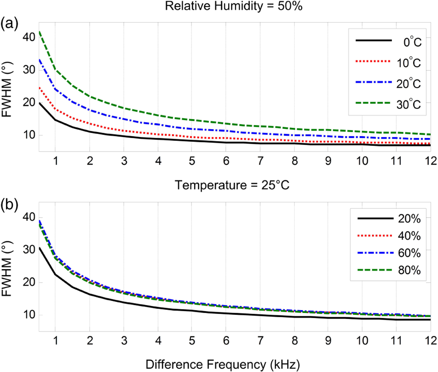
Fig. 7. FWHM of the PAL changing with the temperature and relative humidity.
Figure 8 shows the FWHM of the PAL when the difference frequency is fixed at 4 kHz. The temperature varies from −10°C to 30°C and the relative humidity varies from 5% to 95%. When the air is extremely dry and cold, the beamwidth of the PAL is narrow and independent from the temperature and relative humidity. This is because when the air is extremely dry and cold, attenuation rates of the primary frequencies are so low that the Westervelt's directivity becomes as sharp as the Dirac Delta function. Hence, the convolution model is simplified to the product directivity principle. As aforementioned, the product directivity principle tends to have a narrow beamwidth. On the other hand, when the temperature is high, the beamwidth of the PAL is relatively wide. We can conclude from Fig. 8 that the beamwidth of the PAL is relatively narrow in the desert region and wide in the tropical region. This knowledge of difference in directivity is beneficial to applications of the PAL related to sound field control [Reference Aoki, Toba and Tsujita17–Reference Tanaka, Shi and Kajikawa22].
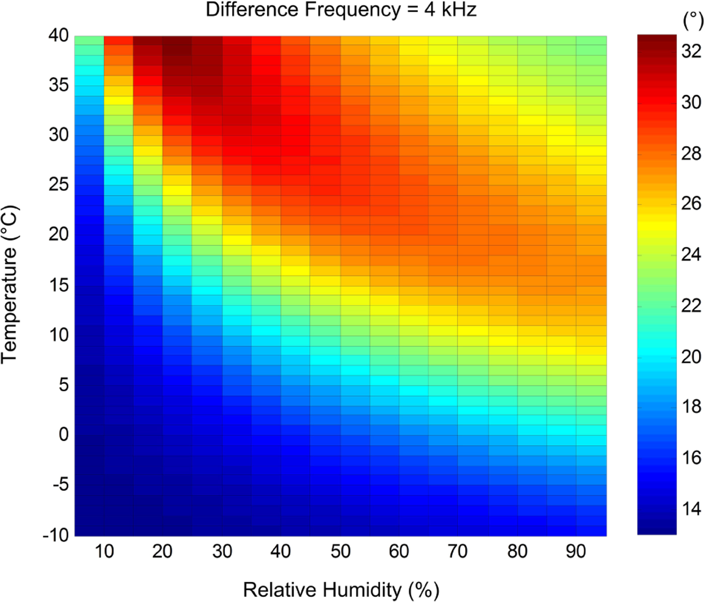
Fig. 8. FWHM of the PAL under different environmental conditions when the difference frequency is transmitted at 4 kHz.
B) Constant beamwidth beamformer of the PAL
In signal processing, the design of a finite impulse response filter based on window functions is a mature and simple technique. Similarly, window functions can be used in the design of a uniform linear array (ULA). When coefficients of a window function are adopted as weights for the ULA, the frequency response of the window function gives the beampattern of the ULA. Hence, the wavenumber is also referred to as the spatial frequency.
The Dolph–Chebyshev window is famous for having the narrowest mainlobe when the sidelobe attenuation is given. Moreover, sidelobe levels of the Dolph–Chebyshev window are always equal. When weights for a ULA are designed based on the Dolph–Chebyshev window, the beamwidth of the ULA is decided by the sidelobe attenuation and vice versa. The emitter of the PAL can be configured into a ULA. Therefore, the constant beamwidth beamforming approach has been proposed for the PAL taking into account the single sideband modulation method [Reference Yang, Gan, Tan and Er55]. In the single sideband modulation, there are two primary frequencies that are referred to as the carrier and sideband frequencies, respectively. In the constant beamwidth beamformer of the PAL, the sidelobe attenuation of the carrier frequency is determined by the given null to null beamwidth, and the sidelobe attenuation of the sideband frequency is adjusted to make the first sidelobe of the sideband frequency coincide with the first null of the carrier frequency. Based on the product directivity principle, the null to null beamwidth of the PAL is equal to the given null to null beamwidth over all the difference frequencies.
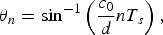
To examine the constant beamwidth beamformer using the convolution model, the PAL consisting of 8 channels is adopted again, of which the interchannel spacing is set to 0.5 cm. This interchannel spacing is feasible only in the compact configuration [Reference Tanaka and Tanaka44, Reference Wu, Wu, Huang and Yang45]. The difference frequency is generated as a sine sweep from 1 to 12 kHz. The lower sideband modulation (LSB) method sets one primary frequency at 40 kHz as the carrier frequency and decreases the other primary frequency from 39 to 28 kHz as the sideband frequency. The null to null beamwidth of the PAL is given by 40°. The steering angle is set to 0°. The design of the constant beamwidth beamformer gives the weight for every channel. Directivities of the difference frequency are plotted in Figs. 9(a) and 9(b) using the product directivity principle and convolution model, respectively. The constant null to null beamwidth is easily observed in Fig. 9(a), but there are no nulls in the convolution model as a result of the convolution with the Westervelt's directivity. Since the convolution model is proved more accurate than the product directivity principle, the FWHM is a more practical measure of the PAL's beamwidth rather than the null to null beamwidth.
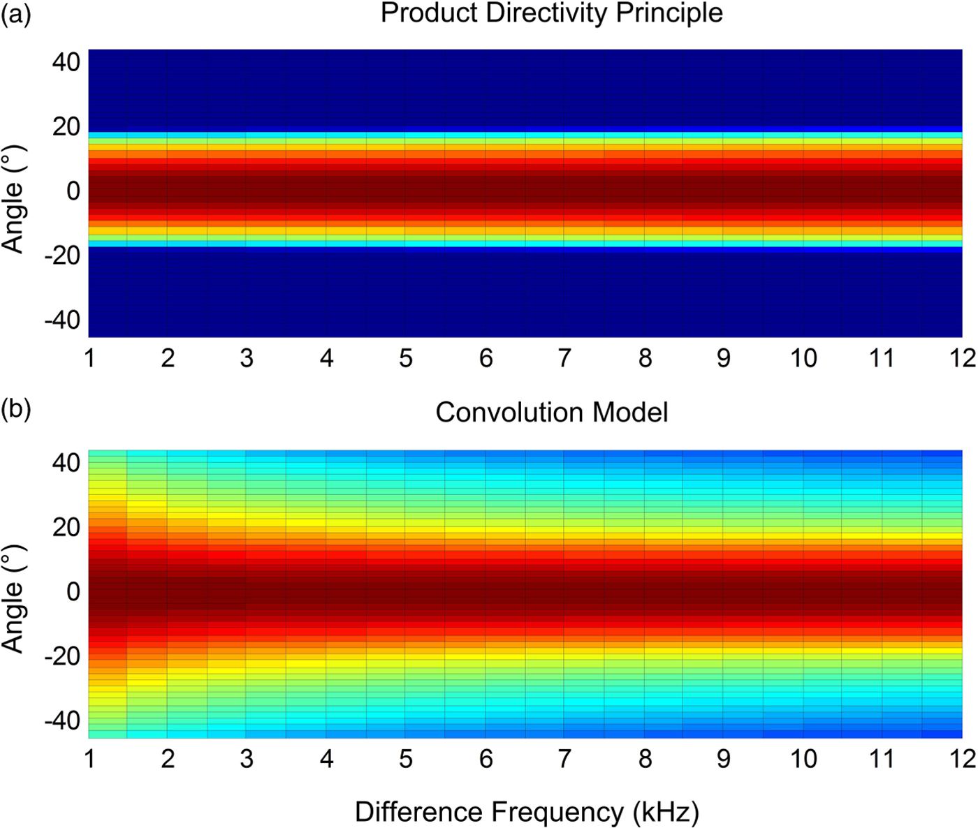
Fig. 9. Directivity of the PAL using the constant beamwidth beamformer.
In contrast to the LSB method, the upper sideband modulation (USB) method increases the sideband frequency from 41 to 52 kHz. FWHMs are measured in directivities of the PAL when the LSB and USB methods are adopted and results are shown in Fig. 10. There are several interesting observations. Firstly, the product directivity principle results in narrower FWHMs as compared to the convolution model. Secondly, when the difference frequency increases, the Westervelt's directivity becomes narrower and model results of the product directivity principle and convolution model become closer. Thirdly, the Westervelt's directivity plays a dominant role in the directivity of the PAL when the difference frequency is low. Lastly, the FWHM of the Westervelt's directivity exhibits an exponential decay against the difference frequency. The convolution model suggests that the product directivity of primary frequencies should be designed to have an exponential growth in the FWHM in order to implement an efficient constant beamwidth beamformer of the PAL.
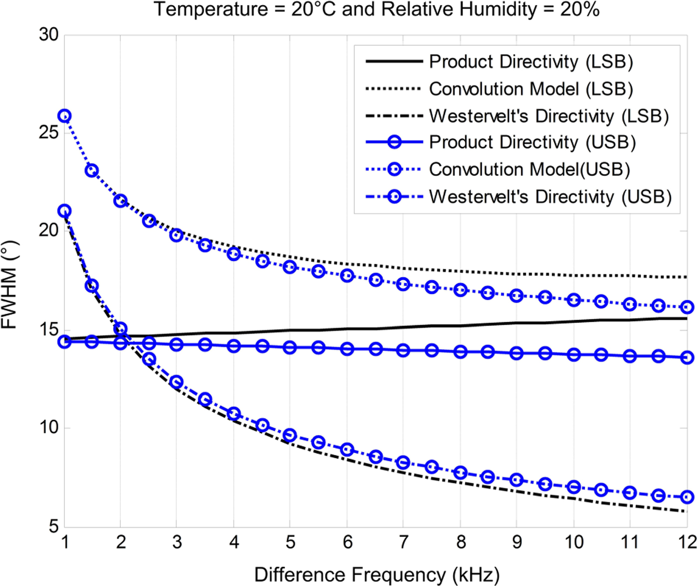
Fig. 10. FWHM of the PAL using the constant beamwidth beamformer.
C) Digital beamsteerer of the PAL
The digital signal is a discrete and discontinuous representation of information. The minimum integer delay in any digital system is determined by the sampling interval of this system. Based on equation (1), the available steering angle is consequently given by
 $$\theta_n = \sin^{-1} \left(\displaystyle{{c_0} \over {d}} {\it nT}_s\right)\comma \;$$
where T s is the sampling interval and n is a natural number. When the interchannel spacing and sampling interval are set to 0.5 cm and 0.01 ms, respectively, there is only one available steering angle existing at 43°. When the interchannel spacing is extended to 1 cm, another steering angle becomes available at 20°, but spatial aliasing also occurs. Derived from equation (17), there are three conventional solutions to the limited range of the steering angle, i.e. to implement the fractional delay filter [Reference Wu, Wu, Huang and Yang45], to use a high sampling rate [Reference Takeoka and Yamasaki46], and to widen the interchannel spacing [Reference Shi and Gan50].
However, these solutions do not account for the sound principle of the PAL. Therefore, a dedicated digital beamsteerer has been specifically worked out for the PAL taking into account the single sideband modulation [Reference Gan, Yang, Tan and Er49]. Different delays are applied to two primary frequencies, which are also referred to as the carrier and sideband frequencies. The carrier signal can be digitally generated with arbitrary delay so the carrier frequency is able to be steered to any direction. However, available steering angles of the sideband frequency remain limited by equation (17). Based on the product directivity principle, if the mainlobe of the sideband frequency is sufficiently wide, the directivity of the carrier frequency will contribute to the directivity of the PAL.
The PAL configuration remains the same as the previous subsection. The carrier and difference frequencies are transmitted at 40 kHz and 4 kHz, respectively. Weights for the sideband frequency are designed by the Parks–McClellan algorithm [Reference McClellan and Parks57]. When the steering angle is set to 20°, directivities of primary and difference frequencies are plotted in Figs. 11(a) and 11(c) when the LSB and USB methods are adopted, respectively. Based on the design of the digital beamsteerer, the mainlobe of the sideband frequency is much wider than the mainlobe of the carrier frequency. Therefore, the steering angle of the PAL is expected to depend on the directivity of the carrier frequency. Furthermore, when the steering angle varies from −90° to 90°, directivities of the difference frequency are plotted in Figs. 11(b) and 11(d). It can be observed that the digital beamsteerer is effective for both the LSB and USB methods until spatial aliasing occurs at large steering angles.
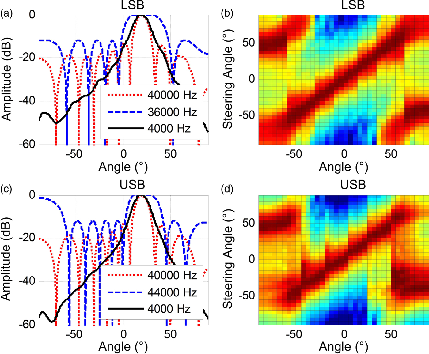
Fig. 11. Directivity of the PAL using the digital beamsteerer and compact configuration.
Because of the wide mainlobe of the sideband frequency, grating lobe elimination is not going to be effective in the digital beamsteerer of the PAL [Reference Shi and Gan50]. Spatial aliasing is thus the weakness of the digital beamsteerer. To illustrate this weakness, the interchannel spacing is extended to 1.5 cm and the rest of conditions are kept unchanged. Now the interchannel spacing is twice the wavelength of the sideband frequency at 44 kHz. When the steering angle is set to 20°, directivities of primary and difference frequencies are plotted in Figs. 12(a) and 12(c). As the grating lobe of the sideband frequency is as wide as the mainlobe, the difference in spatial periods of the carrier and sideband frequencies cannot separate all grating lobes sufficiently. Therefore, grating lobe elimination fails to occur. Once again, when the steering angle varies from −90° to 90°, directivities of the difference frequency are plotted in Figs. 12(b) and 12(c). Spatial aliasing is observed for all steering angles in the digital beamsteerer. It is confirmed that the digital beamsteerer requires a narrow interchannel spacing to avoid spatial aliasing at primary frequencies. Therefore, the compact configuration is of the utmost importance to the digital beamsteerer [Reference Gan, Yang, Tan and Er49].
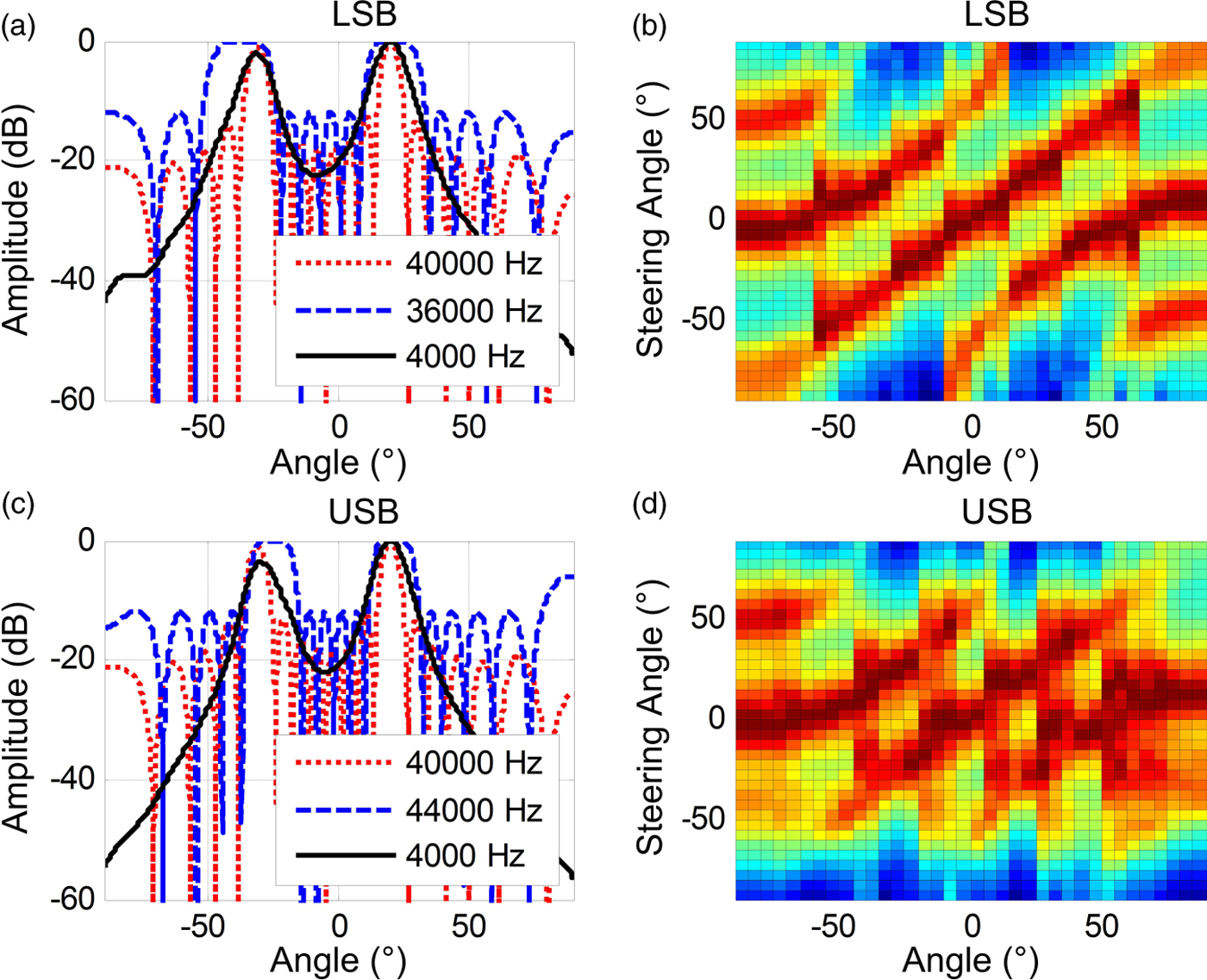
Fig. 12. Spatial aliasing example in the digital beamsteerer of the PAL.
V. CONCLUSIONS
This paper overviewed a wide range of directivity control methods of the PAL. The superb accuracy of the convolution model has been demonstrated through experiments. The convolution model has outperformed previous directivity models. Three applications of the convolution model in the directivity control of the PAL have been elaborated. The directivity of the PAL is found to be relatively narrow in desert regions and wide in tropical regions. The beamwidth of the PAL can double in a hot and humid climate than in a cold and dry climate. Environmental influences on the directivity of the PAL are of importance when the PAL is employed in sound field control. Furthermore, to develop the constant beamwidth beamformer of the PAL, it is suggested that the product directivity have an exponentially growing beamwidth to compensate for the window effect of the Westervelt's directivity in spatial domain. Nevertheless, the directivity of the PAL in the low-frequency band is dominated by the Westervelt's directivity and only mechanical methods are efficient to control it. Lastly, the digital beamsteerer of the PAL has been examined using the convolution model. It is found that the digital beamsteerer is sensitive to spatial aliasing at the primary frequency and thus the compact configuration is of the utmost importance to the digital beamsteerer of the PAL to avoid spatial aliasing.
The convolution model has created new opportunities in the research area of the PAL. There have been many worthwhile attempts to apply the WFS and other sophisticated array signal processing methods to control the directivity of the PAL. But most of them have not been successful due to lack of an efficient directivity model. Trial and error methods of placing PALs in a sound field control application will be improved by introducing the convolution model. We look forward to more exciting applications of the PAL, for example in a smart city where sound field control can be widely applied to reduce noise pollution. This will accelerate the popularity of the PAL. Moreover, as the PAL generates sounds from ultrasound, it is able to be integrated with other established ultrasonic techniques, such as the time reversal, medical imaging, and even parametric receiving array. This paper has thus presented an up to date and comprehensive reference for future works of the PAL.
ACKNOWLEDGEMENTS
This work is supported by MEXT-Supported Program for the Strategic Research Foundation at Private Universities, 2013–2017.
Chuang Shi received his B. Eng. degree in Computer Science from Beijing Jiaotong University in 2005, M. Eng. degree in Microelectromechanical Systems from Tsinghua University in 2008, and Ph.D. degree in Electrical and Electronic Engineering from Nanyang Technological University in 2013. He joined Nanyang Technological University as a research associate and research fellow in 2011 and 2013, respectively. He is currently working as a postdoctoral fellow at Kansai University. He is a member of IEEE and a member of APSIPA. His research interests include parametric array loudspeaker, active noise control, acoustic beamforming, and audio classification.
Yoshinobu Kajikawa received his B. Eng. degree in 1991 and M. Eng. degree in 1993 from Kansai University in Electrical Engineering, and D. Eng. degree in 1997 from Osaka University in Communication Engineering. He worked at Fujitsu Ltd. in 1993 and engaged in research on active noise control. In 1994, he joined Kansai University, as professor. He is a senior member of IEEE and a member of APSIPA. His current research interests fall in the area of signal processing for acoustic and communication systems.
Woon-Seng Gan received his B. Eng. and Ph.D. degrees both in Electrical and Electronic Engineering from the University of Strathclyde in 1989 and 1993, respectively. He joined Nanyang Technological University as a lecturer and senior lecturer in 1993 and 1998, respectively. In 1999, he was promoted to as Associate Professor. He is an AES fellow, a senior member of IEEE, and a member of APSIPA. He has published more than 300 international refereed journal and conference papers. His current research interests include active noise control, audio signal processing, parametric loudspeaker, and spatial audio.


 Open access