

An increasingly heated debate over the future of energy has raged in recent years. The overall challenge – which has become known as the “energy trilemma” – is to simultaneously satisfy three imperatives: affordability, security of supply and decarbonisation. Sadly, resolving the trilemma is proving to be very challenging: it seems that decarbonisation and security of supply can only be achieved at more than twice the current cost of energy, which raises immediate issues of exacerbation of fuel poverty (Younger Reference Younger2014a). Ignoring such complexities, the popular debate (as played out in the press and social media) has tended to over-simplify the issue to a binary choice between fossil fuels, which are characterised as “evil”, and renewables, which are regarded as virtuous. This simplification ignores the crucial point that the most widely-available renewables have little to offer in terms of affordable heat or transport fuels (which together account for 80 % of energy use in Scotland), but produce only electricity, and even that intermittently. Thus, even where a logical progressive step towards decarbonisation is proposed – such as switching fuels from carbon-rich coal to hydrogen-rich natural gas, which results in a halving of carbon emissions per unit of energy converted (McInnes Reference McInnes2011) – such developments are vehemently opposed on the grounds that natural gas is still a fossil fuel. Yet where this switch has already taken place, major reductions in carbon emissions have resulted. This is most notably so in the USA, where carbon emissions have returned to their 1990 levels since the development of shale gas has displaced the burning of coal for power production. Such a rapid lowering of carbon emissions has not been matched even by countries with a far stronger policy commitment to renewables than the USA, such as Scotland, which has so far failed to meet all of its interim annual carbon emissions reduction targets (most recently on 9 June 2015).
Viewed in this light, replacement of coal by gas could make a significant contribution to the progressive decarbonisation of energy supplies in the UK, without sacrificing the security and affordability benefits of fuels of high energy-density in the process (McInnes Reference McInnes2011, Reference McInnes2013; Royal Society of Edinburgh 2015). Yet the preliminary identification of promising shale gas resources in northern England (Andrews Reference Andrews2013) and Scotland (Monaghan Reference Monaghan2014) has met with a very mixed response (Younger Reference Younger2014b). Opponents of shale gas developments have deployed numerous arguments to bolster their case, all of which have been systematically examined by expert review panels convened to advise both the UK and Scottish governments. The UK Government panel (Mair et al. Reference Mair, Bickle, Goodman, Koppelman, Roberts, Selley, Shipton, Thomas, Walker, Woods and Younger2012) focused principally on the environmental risks posed by hydraulic fracturing (or ‘fracking’ as it has now become widely known), most notably induced seismicity and ground water pollution. The Scottish Government panel (Masters et al. Reference Masters, Shipton, Gatliff, Haszeldine, Sorbie, Stuart, Waldron, Younger and Curran2014) was even wider ranging, amounting to a review of the factual (principally peer-reviewed) evidence relating to the industrial context, techniques and wider environmental impacts. This paper does not revisit the detailed findings of these two reports, nor subsequent debates in the peer-reviewed literature over the full range of specific risks, such as induced seismicity (Westaway & Younger Reference Westaway and Younger2014), borehole integrity (Davies et al. Reference Davies, Almond, Ward, Jackson, Adams, Worrall, Herringshaw, Gluyas and Whitehead2014; Thorogood & Younger Reference Thorogood and Younger2014) or life-cycle emissions of greenhouse gases and other pollutants (Mackay & Stone Reference MacKay and Stone2013; Bond et al. Reference Bond, Roberts, Hastings, Shipton, João, Tabyldy Kyzy and Stephenson2014; Stamford & Azapagic Reference Stamford and Azapagic2014; Westaway et al. Reference Westaway, Younger and Cornelius2015). Rather, the focus in this paper is on a very particular hydrogeological risk: that freshwater aquifers could be polluted by upward migration of contaminated fluids through vertical fractures induced by the fracking process. This proposition has been widely aired in public, but subjected to few scientific studies to date. This may be because many experienced hydrogeologists instinctively feel this is a non-issue, given the rarity and feeble rates of natural up-flows of brine from deep saline aquifers (e.g., Anderson Reference Anderson1945; Edmunds et al. Reference Edmunds, Robins and Shand1998; Younger et al. Reference Younger2015). The first published attempt to model the problem (Myers Reference Myers2012) was very poorly posed, with unreasonable boundary conditions and shale permeabilities, and inappropriate representation of key processes and geological features (Carter et al. Reference Carter, Kresic, Muller and Vittorio2013). Unsurprisingly, that study yielded widely-criticised conclusions (Saiers & Barth Reference Saiers and Barth2012; Carter et al. Reference Carter, Kresic, Muller and Vittorio2013; Jackson et al. Reference Jackson, Gorody, Mayer, Roy, Ryan, Van Stempvoort, Kasperson and Renn2013; Flewelling & Sharma Reference Flewelling and Sharma2014) which are wildly inconsistent with known stratigraphy and fluid dynamics in the study region (Appalachia). To date, no similar study has been attempted for any UK setting, with published discussion restricted to a brief statement of hydrogeological principles (Younger Reference Younger2014b). Yet, given the heated public debate on this issue, it is important that all reasoning be clearly explained and presented for discussion; that is the spirit in which this paper is offered. It also focuses particularly on considerations relevant to the Carboniferous strata of Scotland and northern England, which includes most of the stratigraphic units considered prospective for shale gas in that region (cf. Andrews Reference Andrews2013; Monaghan Reference Monaghan2014).
It should be noted that other potential ground water pollution pathways not discussed in this paper could also be associated with shale gas operations, for instance:
(i) Unintentional migration of shale gas well bore fluids into freshwater aquifers at shallow depth, via cracks in steel well casing and/or voids in the cemented annulus which seals the gap between casing and wall rock (see Davies et al. Reference Davies, Mathias, Moss, Hustoft and Newport2013; Jackson et al. Reference Jackson, Gorody, Mayer, Roy, Ryan, Van Stempvoort, Kasperson and Renn2013; Thorogood & Younger Reference Thorogood and Younger2014).
(ii) Accidental spillages of polluting substances at surface, much as might occur at an industrial plant of any sort (Mair et al. Reference Mair, Bickle, Goodman, Koppelman, Roberts, Selley, Shipton, Thomas, Walker, Woods and Younger2012; Masters et al. Reference Masters, Shipton, Gatliff, Haszeldine, Sorbie, Stuart, Waldron, Younger and Curran2014; Westaway et al. Reference Westaway, Younger and Cornelius2015).
As they have been discussed in detail in the works cited, this paper does not consider these two (or any further) ground water pollution pathways, except where they directly interface with the pathway on which this paper focuses: the risk of pollutant migration from deep shale gas fracking zones, up through the intervening strata, into shallower freshwater aquifers.
1. Overview of fracking process
In order to provide context and essential terminology for the rest of the paper, a brief summary of shale gas and fracking is warranted. The summary which follows is condensed and adapted from the explanations given in the report of the Scottish Government's Independent Expert Panel on Unconventional Oil and Gas (on which the author served), which was convened in 2013 and which reported in 2014 (Masters et al. Reference Masters, Shipton, Gatliff, Haszeldine, Sorbie, Stuart, Waldron, Younger and Curran2014).
Conventional oil and gas deposits are contained in porous reservoirs (often limestone or sandstone) which have interconnected pore spaces. These interconnected pores give rise to permeability which allows the oil or gas to effectively flow through the reservoir to the well (synonymous with ‘borehole’ in this context). The reservoir is usually trapped below a low permeability layer and, laterally, by low permeability faults or strata. In contrast, unconventional oil or gas deposits (such as shale gas, shale oil and coal-bed methane) are contained in just such low permeability strata. Furthermore, oil and gas in unconventional reservoirs is frequently present at less than hydrostatic pressure (i.e., “under-pressured”), and so will not flow into wells until these are extensively depressurised by pumping. This means that the lurid image of an oil “gusher” – immortalised in Hollywood movies – is inapplicable to many unconventional reservoirs. More importantly, it also means that oil and gas in unconventional reservoirs are not amenable to recovery by conventional production techniques.
The existence of unconventional resources has been known for many years, but they have only become commercially recoverable on a large scale in the last decade or so. The impulse for this was primarily economic, as global oil prices had been rising for many years (until the abrupt slump in 2014). Commercial viability coincided with recent technical advances in two pre-existing downhole technologies, which made them cost-effective for gas shale applications (Fig. 1).
(i) Directional drilling, which means deviation of the drill-bit from the vertical in a controlled manner, such that different zones of an actual or potential reservoir can be accessed from a single wellhead at surface. The technique is well known in the Scottish conventional oil and gas sector, as it is routinely used in the North Sea.
(ii) Hydraulic fracturing (‘fracking’), which is the artificial fracturing of the reservoir rock in order to increase its permeability. This is generally achieved by injecting fluid into the well at high pressure to create and propagate fractures a designed distance into the surrounding reservoir rock formation. In shale, the injected ‘fracking fluid’ is mainly water (ca. 95 %) containing small quantities of sand or similar particulate matter, referred to as the ‘proppant’, which serves to prop open the fractures. Small quantities of other additives may also be used to keep the proppant in suspension, increase lubrication, lower fluid viscosity and inhibit clogging of newly-opened fractures by microbial biofilms. The fractures created by the technique may only be a few micrometres in width and are usually limited in length to a few tens of metres. Technical advances, particularly over the last decade, have allowed the extent of the fractures to be more accurately predicted, controlled and remotely monitored using micro-seismic techniques, thus increasing the accuracy and effectiveness of the technique. Again, fracking is nothing new in the Scottish oil and gas sector, being widely applied to improve production in mature North Sea reservoirs. It is also familiar onshore, being used (for instance) to attain sufficient yields in water wells penetrating low-permeability bedrock in the Scottish Highlands (Cobbing & Ó Dochartaigh Reference Cobbing and Ó Dochartaigh2007).
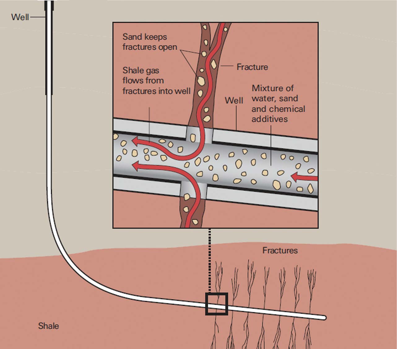
Figure 1 Simplified cross-section (NOT to scale) illustrating the principal processes which constitute hydraulic fracturing (‘fracking’) of shale to produce shale gas.
Having directionally drilled into a gas shale, and injected fluid to hydraulically fracture the rock, gas production requires a further step: the head of water in the borehole must be drastically reduced (often by pumping the fluid level all the way down to the shale horizon) until the partial pressure of the gas in the fractured zone exceeds the head of fluid in the borehole, so that gas can finally enter the well and rise to surface where it is captured and dispatched for marketing. The water pumped out of shale gas wells during this process is termed ‘flow-back fluid’ or ‘returned water’, and it typically comprises a mixture of the injected fluid plus native pore water from the fractured shale strata. The nature of flow-back fluids is considered further in section 4.2.1 below.
2. Risk assessments and public perceptions
This study considers a hydrogeological risk. It uses hydrogeological principles, observations and data to generically evaluate the risk of pollutant migration from deep shale gas fracking zones to shallower freshwater aquifers. This does not eliminate the need for site-specific risk assessments, but should provide a framework to facilitate them. Such generic risk evaluations are nothing new in hydrogeology; similar evaluations have been made of risks as diverse as ground water pollution by infiltration of contaminated water from agricultural or post-industrial land (e.g., Swartjes Reference Swartjes1999), radioactive waste disposal (e.g., Rechard Reference Rechard1999) and acidic mine drainage (e.g., Younger et al. Reference Younger, Coulton and Froggatt2005).
While technical risk assessments are essential, they are but an initial step in a broader social dialogue around the acceptability of proposed activities. However, an awkward disconnect frequently attends efforts to introduce technical risk assessments to the lay public. In many cases, risks that are assessed as relatively minor by technical specialists become amplified during their passage through various stages of social discourse (Kasperson et al. Reference Kasperson, Renn, Slovic, Brown, Emel, Goble, Kasperson and Ratick1988). The psychological, sociological and cultural factors which contribute to such amplification of risk are complex and not always amenable to deliberative refinement. This would appear to be due to an effective cessation of dialogue once trust in decision makers has been broken. It has been observed that such trust is particularly fragile in participatory democracies (Slovic Reference Slovic1993). Measures intended to foster greater trust, such as freedom of information legislation, have often turned out to be counter-productive in the face of their aggressive use by the press and social media campaigns to identify any snippets of information which can be construed as revealing disingenuousness on the part of decision makers (cf. Greenberg Reference Greenberg2014).
Recent public controversies over a wide range of energy developments, including wind farms and carbon capture and storage, have confirmed the central importance of trust in this context too (e.g., Howell et al. Reference Howell, Shackley, Mabon, Ashworth and Jeanneret2014). It is therefore no surprise that analysis of the public discourses around shale gas in the USA (Boudet et al. Reference Boudet, Clarke, Bugden, Maibach, Roser-Renouf and Leiserowitz2014) and the UK (Cotton et al. Reference Cotton, Rattle and Van Alstine2014) reveal that a lack of trust is also hindering dispassionate consideration of the merits and demerits of the technology. The roots of such mistrust lie largely in a series of legislative changes introduced in the USA, commencing with the Energy Act 2005, which effectively exempted shale gas operations from a swathe of long-standing federal environmental protection laws (Mair et al. Reference Mair, Bickle, Goodman, Koppelman, Roberts, Selley, Shipton, Thomas, Walker, Woods and Younger2012). This rather clumsy manoeuvre on behalf of the nascent shale gas sector immediately begged the question: “What is so bad about shale gas that it requires exemption from environmental regulation?” This is a reasonable question, yet it has received insufficient answer from the oil and gas sector in the USA (Boudet et al. Reference Boudet, Clarke, Bugden, Maibach, Roser-Renouf and Leiserowitz2014). In the absence of true dialogue, once public suspicions were aroused, almost any observed or suspected instances of environmental degradation (as well as any minor ailments amongst local residents) were popularly attributed to shale gas operations. In our era of instant global sharing of information and opinions via social media, the resultant climate of mistrust crossed the Atlantic before the first shale gas borehole in the UK had even been proposed.
Contrary to popular belief, the UK has a long (if poorly documented) history of fracking of onshore conventional oil and gas wells, stretching back several decades (Mair et al. Reference Mair, Bickle, Goodman, Koppelman, Roberts, Selley, Shipton, Thomas, Walker, Woods and Younger2012). It is estimated that around 200 such fracked wells have been operated in the UK since the 1960s, without a single reported incident of ground water pollution (Thorogood & Younger Reference Thorogood and Younger2015). Furthermore, wells drilled for other purposes have also been fracked, such as public water supply wells in the Scottish Highlands (Cobbing & Ó Dochartaigh Reference Cobbing and Ó Dochartaigh2007). To date, however, only a single shale gas well has been fracked in the UK, at Preese Hall in Lancashire (National Grid Reference [SD 37532 36627]), and this led to two small seismic events, of local magnitudes (ML) 1.5 and 2.3 (Westaway & Younger Reference Westaway and Younger2014). Given these modest magnitudes, neither event caused any damage at surface, nor was reported as having been felt by any member of the public until their geophysical detection was announced by the British Geological Survey. Thereafter, a public outcry ensued, prompting the UK Government to impose a temporary moratorium on further shale gas fracking, pending an investigation of the safety of shale gas by a purpose-convened expert panel (Mair et al. Reference Mair, Bickle, Goodman, Koppelman, Roberts, Selley, Shipton, Thomas, Walker, Woods and Younger2012). From any point of view, this was an inauspicious debut for UK shale gas fracking, and the subsequent controversy has showed little sign of abatement. The extensive investigations of two independent expert panels, both of which concluded that shale gas fracking could be pursued safely, provided the existing UK regulatory framework was properly applied (Mair et al. Reference Mair, Bickle, Goodman, Koppelman, Roberts, Selley, Shipton, Thomas, Walker, Woods and Younger2012; Masters et al. Reference Masters, Shipton, Gatliff, Haszeldine, Sorbie, Stuart, Waldron, Younger and Curran2014), had little impact on public opinion.
Although the UK moratorium was lifted following the Government's acceptance of the joint Royal Academies' report (Mair et al. Reference Mair, Bickle, Goodman, Koppelman, Roberts, Selley, Shipton, Thomas, Walker, Woods and Younger2012), a lack of trust continues to characterise the public debate on shale gas. In Scotland, a further moratorium on shale gas (and coalbed methane) developments was introduced in February 2015, with the Scottish Government setting aside the clear findings of the independent expert panel, which they themselves had convened, in favour of the opponents' argument that shale gas fracking ought not to proceed until it can be proven that it poses no risks in the particular geological and environmental conditions of Scotland (Younger Reference Younger2015). Empirically proving that a given activity will not have a particular effect is impossible when that activity is not happening, of course. So, are there any analogous activities that might be used to elicit the necessary degree of comfort? As previously mentioned, a few conventional onshore gas wells have previously been fracked without incident in Scotland; for instance, the 1300m-deep Salsburgh 1A well near Airdrie ([NS 7918 6378]; British Geological Survey well record no. NS86SW89). This commenced on the Lower Coal Measures outcrop and penetrated a cyclothemic sequence of clastics, coals and limestones (corresponding to the Clackmannan Group and upper Strathclyde Group), terminating in the tuffaceous clastics which appear to belong to the Kirkwood Formation (Lower Carboniferous). This well was fracked by BP in 1964 and successfully produced gas for several years before later being plugged with cement and abandoned (Smith et al. Reference Smith, Bide, Hyslop, Smith, Coleman and McMillan2008). It might be hoped that evidence from such operations could be used to provide the further reassurance that the Scottish Government is seeking. However, the few such boreholes in Scotland were constructed in an era when no statutory recording of fracking operations was required and when there was no requirement for synchronous monitoring of any shallow aquifers. Despite the fact that no problems have been reported from these sites, the absence of detailed documentation means it will be impossible to use them as definitive case-studies. It therefore seems that the only way to directly demonstrate that shale gas fracking could be done in Scotland would be by thoroughly documenting a few new shale gas well operations – yet these are banned under the current moratorium. The emergence of any unconventional gas industry in Scotland would thus appear to be precluded by a classic ‘Catch-22’ situation.
Yet there does exist a wealth of analogical information relating to an even greater example of subsurface disruption in the UK, from which valuable lessons may be drawn which may be considered to be analogous to the issues raised by fracking: longwall coal mining beneath aquifers. Before examining this analogue (sections 5 and 6), it is appropriate to summarise the argument made by the opponents (section 3) and to examine it using prima facie hydrogeological reasoning (section 4).
3. Hypothesis: fracking might cause ground water pollution
As previously noted, this paper focuses on just one of the possible pathways via which gas and/or liquids present in shale gas wells might give rise to pollution of shallow, freshwater aquifers. Those other pathways are not related to fracking per se – they could equally apply to oil/gas wells exploiting conventional reservoirs and, in the case of surface spillages, to industrial operations of any nature whatsoever.
The hypothesis examined in this paper is that fracking fluids, flow-back fluid and/or gas, present at depth in a shale gas well, might migrate upwards through the overlying strata (‘overburden’) and enter freshwater aquifers, polluting them. This upward migration might occur via natural pore space, fractures induced by the fracking process itself and/or via natural fractures which have been rendered more permeable by fracking.
4. Hydrogeological evaluation: prima facie reasoning
4.1. Governing principles of pollution risk assessment for ground waters
Since the late 1990s, the hydrogeological community has been successfully applying a standardised approach to ground water pollution risk assessment, known as the ‘source-pathway-receptor’ model (e.g., Ferguson Reference Ferguson1999). This approach is simple, yet powerful: it requires identification of a potential pollution source (e.g., a body of contaminated land or a disused landfill) and one or more sensitive receptors (e.g., a fragile ground water-dependent ecosystem or a potable water supply well). If only one of these two exists, no pollution risk exists; if both exist, then a pollution risk may exist – but only if a credible ‘pathway’ links the source to the receptor. A ‘pathway’ in this context means a ground water flow-path along which pollutants originating in the source could be moved, principally by advection (i.e., as solutes or colloids carried by the bulk movement of the ground water itself). (Transport by diffusion down chemical gradients, according to Fick's Law, is sufficiently slow that it could only be negligible over the spatial and temporal scales of reference in this context). The identification of advective pathways involves assessment of two factors:
• Identification of potential hydraulic connectivity, which is done by assessing the hydrostratigraphy of the system (i.e. the classification of the local lithostratigraphic sequence into aquifers and aquitards; Younger Reference Younger2007) and any permeable joint or fault planes which might provide localised connectivity between otherwise separate aquifers.
• Assessment of the hydraulic gradients within and between the aquifer(s) that lie(s) between the source and the receptor. A ‘hydraulic gradient’ is the variation in hydraulic head (also known as ‘ground water head’, ‘groundwater potential’ and ‘piezometric head’) along a flow path. Hydraulic head is the summation of absolute elevation (usually measured relative to sea level) and pore water pressure. It is best measured by means of piezometers/monitoring wells, although much can be gleaned from geomorphological evidence (e.g., Younger Reference Younger, Rose and Mather2012), such as the elevations of springs and the beds of perennial streams, and even from natural changes in ground water chemistry as flowing water successively encounters strata of different composition and solubility (Younger Reference Younger2007).
If the dispositions of the strata and any permeable faults between a source and receptor are such that hydraulic connectivity is likely, the next step is to determine the polarity of the hydraulic gradient (i.e., the direction of flow) between the two; only where the hydraulic head declines from the source towards the receptor is there any pollution risk. In the opposite case, clean ground water would be flowing from the receptor towards the potential pollutant source zone, so there would be no risk of pollution to that receptor.
Where there is a co-occurrence of hydraulic connectivity and a hydraulic gradient of appropriate polarity, then there is at least some risk of pollution affecting the receptor. It is at this point that the risk assessment becomes more complicated and more quantitative. Essentially, the further quantification of the risk requires estimation of:
1. the rate of movement of polluted ground water from source to receptor (i.e., by advection – the movement of the pollutants with the bulk flow of the moving ground water). This is typically assessed using some variant of Darcy's Law, which tells us that ground water velocity equals the product of the hydraulic conductivity and the hydraulic gradient;
2. any dispersion and/or retardation of pollutants during advective transport. Dispersion is the sum of the effects of mechanical mixing, which arises due to micro-scale deviations in velocity vectors from the bulk value yielded by Darcy's Law, and molecular diffusion (governed by Fick's Law). Retardation is a representation of geochemical reactions (e.g., sorption, ion exchange and dissolution/precipitation reactions) which effectively slow the movement of solutes relative to the advective velocity. The more a pollutant is retarded, of course, the longer the dispersive processes will have to affect it before it reaches the receptor.
These processes are typically accounted for by means of mathematical modelling exercises (e.g., Bear & Cheng Reference Bear and Cheng2010). Adequate accounting for these processes is necessary, because the rate of delivery of pollutants to the receptor controls whether pollution can cause any harm, or even be detected. An illustrative calculation makes the point clearly. Suppose a hydraulic connection (i.e., ‘pathway’) exists between a pollutant source that releases a leachate containing 20 μg/L of cadmium (Cd) and a discrete body of fresh groundwater within an aquifer (the ‘receptor’), which would usually be selected to be a ‘flow-tube’ defined on piezometric grounds (cf. Younger Reference Younger2007). Let's say the flow tube in question naturally transmits 100 m3/d of clean ground water in which no cadmium is present. At such a brisk ground water flow rate, mixing could be assumed to be fairly rapid, swiftly distributing contaminants evenly throughout the ground water flow tube. Assuming a typical laboratory detection limit for cadmium of 0.1 μg/L and a maximum permitted concentration in fresh ground water of 3 μg/L, we can calculate how much inflow of the leachate would be required to make the cadmium at least detectable, if not in breach of the maximum permitted concentration. For the sake of this illustration, it will be conservatively assumed that leachate traverses the pathway by ‘plug flow’, i.e., solely by advection, with no reduction of cadmium concentrations by dispersion or retardation, so that the cadmium concentration of leachate entering the receptor is the same as that at source (20 μg/L). Using the simple and well-known binary mixing model for two waters (e.g., Faure Reference Faure1998) it is readily demonstrable that about 5.5 m3/d (=0.064 L s–1) of leachate would need to be entering the receptor for cadmium concentrations to reach the detection limit, and that the maximum permissible concentration would only be exceeded when leachate inflow rate reached about 18 m3/d (=0.208 L s–1). Were we to fully account for the dispersive and retardation processes along the pathway, then these inflow rates would have to increase. This simple example shows that significant amounts of polluted leachate could in fact be entering the aquifer before it would become demonstrably polluted.
In practice, uncertainties in various governing parameters mean that it is more logical to undertake calculations of pollutant inflow rates and concentrations probabilistically (e.g., Sudicky et al. Reference Sudicky, Illman, Goltz, Adams and McLaren2010). This entails defining both the input and output parameter sets as probability density functions. This has the further advantage that predictions are reported directly as probabilities, which is in any case the most appropriate format for risk estimates (e.g., Sherwood & Younger Reference Sherwood, Younger and Chilton1997).
4.2. Source–pathway–receptor assessment of shale gas pollution risks
Application of this approach to the case of shale gas is simple enough at the generic level: what can be said about the source, pathway(s) and receptor(s)?
4.2.1. Source
Fracked zones of shale contain different fluids at different times. At the time of injection, they are occupied for a few hours by the fracking fluid itself. As noted in section 1, this is essentially fresh water (ca. 95 %) carrying small loadings of quartz or similar particulate matter (e.g., ceramic beads), which act as the proppants to hold fractures open (Fig. 1), together with small quantities of lubricants, viscosity modifiers and (if the water used was not already disinfected, as would be the case for chlorinated tap water) some anti-bacterial agent. The resultant fracking fluid mixture is typically not hazardous in itself (e.g., Mair et al. Reference Mair, Bickle, Goodman, Koppelman, Roberts, Selley, Shipton, Thomas, Walker, Woods and Younger2012; Masters et al. Reference Masters, Shipton, Gatliff, Haszeldine, Sorbie, Stuart, Waldron, Younger and Curran2014), but it has only a brief unadulterated existence within the fracked zone before it mixes with the native pore water to form the ‘flow-back fluid’ which must then be pumped from the well to depressurise the fracked zone and allow gas production to occur (cf. section 1). Because the pore water which mixes with the fracking fluid is typically very ancient (possibly as old as the shales themselves), and has been effectively immobile for a large interval of geological time, it has usually reacted so extensively with the enclosing minerals that it is rather saline. Hence, flow-back fluids in turn are typically saline. For instance, Jackson et al. (Reference Jackson, Gorody, Mayer, Roy, Ryan, Van Stempvoort, Kasperson and Renn2013) describe flow-back fluids from three of the major shale gas reservoirs in the USA as being Na–Cl waters with total dissolved solids (TDS) concentrations of 15.2–39.6 g/L. The flow-back fluids at the only shale gas well to be fracked in the UK to date (Preese Hall Well 1, Lancashire, [SD 37532 36627]) were even more saline, with a TDS (estimated from specific electrical conductance measurements reported by Broderick et al. Reference Broderick, Anderson, Wood, Gilbert, Sharmina, Footitt, Glynn and Nicholls2011) of 86.9–97.9 g/L. These compositions are well within the usual range encountered in co-produced waters from conventional hydrocarbon reservoirs worldwide, including in the UK (e.g., Warren & Smalley Reference Warren and Smalley1994), and indeed with natural saline springs and geothermal waters encountered in northern England (Younger et al. Reference Younger, Boyce and Waring2015). However, like all of these other natural waters, their very salinity renders them undesirable for mixing with water in fresh water aquifers, lakes, streams or rivers (cf. Manning et al. Reference Manning, Younger, Smith, Jones, Dufton and Diskin2007).
Most mudstones naturally contain relatively elevated concentrations of various radionuclides; indeed, this attribute is routinely used to identify mudstones on borehole logs by their natural gamma emissions. Dissolution of radioisotopes in flow-back fluids can therefore result in the occurrence of a range of ‘naturally occurring radioactive materials’ (NORMs) in solution; this was the case in the Preese Hall Well 1 flow-back fluid, for instance (Almond et al. Reference Almond, Clancy, Davies and Worrall2014). The dissolved concentrations themselves are not high enough to be hazardous, but they can be selectively concentrated into the solid phase by co-precipitation in scales on pipework, etc.; sometimes reaching levels at which special handling is required when disposing of the affected infrastructure. Again, this is nothing new to the Scottish hydrocarbons sector, as the same issues with NORMs occur in offshore rigs (Masters et al. Reference Masters, Shipton, Gatliff, Haszeldine, Sorbie, Stuart, Waldron, Younger and Curran2014).
In summary, the fracked zones of shale gas reservoirs can be expected to contain saline waters, possibly with elevated concentrations of NORMs, which could prove problematic if they entered a sensitive receptor such as a fresh water aquifer. Fracked zones also contain gas, of course, though this is only significantly mobile once the flow-back water has been removed by pumping.
4.2.2. Pathway
As explained in section 4.1, for a pathway to exist there must be a permeable connection through the strata and a suitable driving head. As regards permeable connections, it is important first to be clear on dimensions. Most shale gas prospects in the UK are at depths of 2 km or more (Andrews Reference Andrews2013; Monaghan Reference Monaghan2014). In contrast, fresh ground water circulation seldom extends deeper than about 200 m; the guidelines on defining and reporting on bodies of fresh groundwater adopted by the UK Technical Advisory Group on the Water Framework Directive err heavily on the side of caution by assuming a maximum depth of 400 m (UKTAG 2012). Hence, any pathway along which pollutants might move from fracked shale zones to sensitive receptors must be hydraulically continuous over vertical intervals in excess of 1600 m. Three possible pathways can be envisaged, each of which must be examined for their ability to convey pollutants over such a vertical interval: (i) through the natural permeability of the shale and overburden; (ii) via natural faults and other fractures penetrating the overburden; and (iii) through the fractures artificially induced by the fracking process itself. Taking each of these possible pathways in turn:
(i) The natural permeability of deeply-buried shales has been studied extensively, principally in the context of characterising them as ‘caprocks’ which prevent upward migration of oil and gas from more permeable underlying strata. Reported values range from 2.4×10⁻²² to 9.5×10⁻¹⁹ m2 (Yang & Aplin Reference Yang and Aplin2007). It is axiomatic that, as caprocks (which correspond to ‘aquitards’ in hydrogeological terminology), the natural permeabilities of shales are far too low to allow fluid migration over the requisite vertical intervals on timescales of less than millions to hundreds of millions of years (Flewelling & Sharma Reference Flewelling and Sharma2014). This is reinforced by the fact that the ratio of horizontal to vertical permeability in these shales ranges from 1.7 to 11.8 (Yang & Aplin Reference Yang and Aplin2007), which means that horizontal flow is highly preferential over vertical flow. Even where more permeable strata occur in the overburden, the throttling effect of the lowest permeability strata in the sequence will dominate the effective transit time. Clearly then, migration via natural permeability over timescales of relevance to human investigations (decades), or indeed to the atmospheric residence times of greenhouse gases (centuries), is infeasible and can be discounted.
(ii) Natural geological faults are known to serve as preferential conduits for ground water flow in various environments. Equally, faults are frequently found to be barriers to ground water flow (Faulkner et al. Reference Faulkner, Jackson, Lunn, Schlische, Shipton, Wibberley and Withjack2010). In recent planning hearings in the UK, public depositions made on behalf of opponents in relation to both coalbed methane (Smythe Reference Smythe2014a) and shale gas (Smythe Reference Smythe2014b, Reference Smythec) claimed that all geological faults should be regarded as permeable unless proven otherwise; it was further claimed that this is the default assumption made in all hydrogeological investigations. In reality, no such default assumption is made in other hydrogeological contexts (Younger Reference Younger2007; Faulkner et al. Reference Faulkner, Jackson, Lunn, Schlische, Shipton, Wibberley and Withjack2010), and none can be claimed to apply to the particular case of gas shales, for at least four reasons:
1. Where faults cut low-permeability strata such as shales (and even locally where the fault passes from a shale into a more permeable bed), there is a marked tendency for the fault plane to be lined with a fine-grained clay-rich material known as ‘fault gouge’, which typically renders these portions of the fault planes effectively impermeable (Younger Reference Younger2007). In contrast, where the same fault cuts a permeable rock such as sandstone (and the displacement has not smeared clay-rich gouge from an over- or under-lying mudstone into the fault zone), then the fault plane may well be occupied by relatively permeable breccia; minor fractures either side of the fault plane in a sandstone might also be relatively clean and open. Thus, the same fault may be relatively permeable where it passes through thick sandstone, yet impermeable where it passes through shales. Hence, there is no a priori reason to suppose that the faults cutting mixed sedimentary sequences will be permeable throughout their depths.
2. Even in prolific aquifers in which fracture flow accounts for most ground water movement, permeability due to the fracturing commonly varies considerably over relatively short distances, indicating a high degree of variability in the ability of fractures to permit flow.
3. The permeability of all faults is subject to modification by the local, present-day crustal stress regime (Carter et al. Reference Carter, Kresic, Muller and Vittorio2013). This tends to favour faults being more permeable where they are aligned fairly closely to the current maximum compressive stress azimuth, but tends to make them far less permeable if they are otherwise oriented (e.g., Ellis et al. Reference Ellis, Mannino, Johnston, Felix, Younger and Vaughan2014). (This proviso does not override the basic permeability control provided by fault gouge.)
4. Faults often occur as en echelon systems of fractures which are seldom hydraulically connected over large distances. Available data suggest that there is only a 15 % chance of hydraulic continuity within a single natural fracture extending over a vertical interval of more than 500 m (Davies et al. Reference Davies, Mathias, Moss, Hustoft and Newport2012), with a maximum recorded extent of 1106 m in natural hydraulic fractures studied in the few oilfields where these are encountered.
5. Even where a fault is continuously permeable over a large vertical interval, ground water flow through the fault plane can only occur if there is a sustained driving head along it. This point is examined below, as it is common to all three possible forms of hydraulic connectivity.
For these and other reasons, the actual consensus amongst hydrogeologists is that faults cannot all be assumed to be permeable. Indeed in many aquifers major faults act as barriers to flow, and there are many examples from the North Sea hydrocarbon province of faults acting as structural traps. Even where faults are permeable, they cannot serve as pathways for upward migration of ground water unless they are subject to a hydraulic head gradient of sufficient magnitude and polarity (e.g., Carter et al. Reference Carter, Kresic, Muller and Vittorio2013). The picture is identical in the case of conventional oil and gas reservoirs. While there are numerous documented examples of natural seepages of oil and gas along fault planes (e.g., Jackson et al. Reference Jackson, Gorody, Mayer, Roy, Ryan, Van Stempvoort, Kasperson and Renn2013), the very existence of myriad hydrocarbon reservoirs in areas affected by ancient faulting demonstrates that such seepage is by no means ubiquitous, let alone inevitable. In summary, faults sui generis are hydrogeologically ambiguous, and there is no substitute for site-specific evaluation (Faulkner et al. Reference Faulkner, Jackson, Lunn, Schlische, Shipton, Wibberley and Withjack2010).
(iii) Artificial hydraulically-induced fractures typically extend a few tens of to a couple of hundred metres from their points of origin (Fisher & Warpinski Reference Fisher and Warpinski2012). Fracture orientations also generally align with the plane normal to the azimuth of minimum compressive crustal stress. At shallow depths, the lack of overburden pressure means that the minimum stress is usually vertical, so that hydraulic fractures propagate horizontally; this tendency is fortuitous, as it minimises the risk of near-vertical inter-connections developing with overlying aquifers. At the depths of 2 km or more which are typical of UK shale gas prospects, the azimuth of minimum stress is typically one of the horizontal axes, so that fracking from deeper boreholes tends to result in predominantly vertical fractures. Vertical fracturing clearly has greater potential to achieve inter-connection with overlying aquifers; however, the chances of a hydraulic fracture propagating for 1600 m or more to the nearest freshwater aquifer (as in UK conditions) are extremely low (Davies et al. Reference Davies, Mathias, Moss, Hustoft and Newport2012, Reference Davies, Mathias, Moss, Hustoft and Newport2013; Fisher & Warpinski Reference Fisher and Warpinski2012; Mair et al. Reference Mair, Bickle, Goodman, Koppelman, Roberts, Selley, Shipton, Thomas, Walker, Woods and Younger2012; Jackson et al. Reference Jackson, Gorody, Mayer, Roy, Ryan, Van Stempvoort, Kasperson and Renn2013; Lacazette & Geiser Reference Lacazette and Geiser2013; Flewelling & Sharma Reference Flewelling and Sharma2014; Younger Reference Younger2014b). For instance, Davies et al. (Reference Davies, Mathias, Moss, Hustoft and Newport2012) reported maximum propagation of hydraulic fractures (as revealed by micro-seismic monitoring) of around 588 m, and commented that “… the probability of a stimulated … hydraulic fracture extending vertically >500 m is ∼1% …” (This conclusion was not significantly altered by a subsequent discussion between Lacazette & Geiser (Reference Lacazette and Geiser2013) and Davies et al. (Reference Davies, Mathias, Moss, Hustoft and Newport2013)).
The results of micro-seismic monitoring of hydraulic fracture propagation in many thousands of fracking operations undertaken beneath fresh water aquifers in the USA (originally presented by Fisher & Warpinski (Reference Fisher and Warpinski2012) and partially reproduced in more accessible publications by Mair et al. (Reference Mair, Bickle, Goodman, Koppelman, Roberts, Selley, Shipton, Thomas, Walker, Woods and Younger2012) and Younger (Reference Younger2014b)) reveal not a single case in which a hydraulic fracture has established connection with the nearest overlying fresh water body. On reflection, this should come as no surprise, as hydraulically connecting a shale gas production zone to a prolific aquifer would result in a massive increase in the amounts of flow-back fluid which would need to be pumped from the gas production wells in order to achieve gas production. This would almost certainly render any shale gas well unusable. It is precisely to avoid any such calamity that shale gas operators record the position of the nearest aquifer when planning their fracking stages – hence, yielding the abundant data presented by Fisher & Warpinski (Reference Fisher and Warpinski2012). So although their motivations differ from those of groundwater protection professionals, shale gas developers have just as great a vested interest in avoiding creating inter-connections between fracked zones in shale and overlying aquifers. Rather than conflicting interests, therefore, this is a case of a confluence of interests.
With regard to the driving head, it is important to consider both the in situ pressure regime and the transient regime introduced by fracking and depressurisation (see section 1). Where conventional oil and gas reservoirs occur, the in situ pressures in the reservoirs may initially exceed hydrostatic head, thus giving rise to the oil ‘gushers’ and blow-outs so beloved by Hollywood. Such reservoirs are termed “over-pressured”. Over-pressure would always give rise to surface seepages of hydrocarbons if they were connected to the surface by permeable pathways. In other words, conventional reservoirs only occur where there are insufficient permeable pathways to the surface to have allowed dissipation of fluid pressure over geological time. In contrast, most unconventional reservoirs are “under-pressured”, so that the initial in situ pressure is less than hydrostatic, and thus incapable of giving rise to surface seepages. Together with low permeabilities, this under-pressurisation necessitates the reservoir stimulation and depressurisation activities typical of shale gas operations (Mair et al. Reference Mair, Bickle, Goodman, Koppelman, Roberts, Selley, Shipton, Thomas, Walker, Woods and Younger2012).
The transient sequencing of shale gas fracking operations (see section 1) gives rise to a transient pressure regime in the fracked zones. The period of time during which pressure is raised in the target shales so that hydraulic fracture actually occurs is measured on a scale of hours (Saiers & Barth Reference Saiers and Barth2012). During this interval, the hydraulic head within the fracked zones will exceed both the hydrostatic and the lithostatic head, and there will thus be a temporary net-upward hydraulic gradient. As soon as fractures form, however, the magnitude of this gradient will decrease sharply in response to the increased permeability. Given the low permeabilities of intact shale beyond the fracked zone (Yang & Aplin Reference Yang and Aplin2007), the few hours during which the hydraulic gradient is elevated is many orders of magnitude too brief a period to result in a net transfer of fracking/flow-back fluid up to aquifers located more than a thousand metres above (Flewelling & Sharma Reference Flewelling and Sharma2014). After completion of all of the sequential frack ‘stages’ (i.e., fracturing episodes of adjacent portions of the shale accessed by a particular lateral branch of a well), a sustained period of head lowering ensues, which typically endures for as many years as the shale gas well is operative. During this extended period of time (by far the longest interval in the life of a shale gas well), the net hydraulic gradient will be oriented downwards, towards the nearest lateral section of the production well. (It is the fear of combining this downward head gradient with hydraulic connectivity to an aquifer which motivates shale gas operators never to create inter-connecting fractures.)
During this period, the fracked zones are stripped of most of the flow-back fluid they once contained, and the gas present in the shale becomes the principal fluid flowing to the production wells. However, as the pressure of this gas is (by definition) insufficient to overcome the natural hydrostatic pressure, it cannot be considered a potential pollutant likely to flow up through overlying strata which remain at pressures close to hydrostatic. Eventually, reducing gas yields will lead to a situation in which even the small amount of residual water pumping required to maintain gas production is no longer worthwhile. At this point, pumping will cease and the well will be scheduled for abandonment. When pumping ceases, what little ground water is still flowing into the fracked shale gas zone will gradually accumulate under gravity such that the fracked zone is flooded and the water head in the well begins to rise, slowly reducing the magnitude of a hydraulic gradient that will still be oriented downwards. Left to achieve equilibrium, this process would likely require centuries. However, as UK regulations require any abandoned oil or gas well to be tightly plugged with cement as soon as production ceases (typically within weeks of the end of gas production), the zone of depleted head will be ‘locked in’ at depth behind a column of cement which is both stronger and less permeable than the intact shale. Even when the head has finally equilibrated in the fracked zones, the overall hydrogeological regime will be dominated by the extremely slow movement of ground water through the intact shale up-dip and above the fracked zone, and development of a head in the fracked zone in excess of hydrostatic head would (if it ever occurred) likely require centuries or millennia. Even then, any upward flow of brine from the isolated permeable zones at depth would be constrained by the low permeability of overlying undisturbed strata, and would thus occur no faster than under pre-development conditions, with transit times of the order of millions of years (Flewelling & Sharma Reference Flewelling and Sharma2014). Any such upflow would tend to deliver brine into shallow aquifers at such a slow rate that it would be undetectable (cf. section 4.1).
In summary, of the three potential sources of hydraulic connectivity, the features with the greatest potential to offer connectivity to shallow freshwater aquifers are natural faults, particularly if their permeabilities are locally enhanced by interaction with hydraulic fractures. However, available data suggest that continuously permeable pathways through faults over distances in excess of 1,600 m are very rare in settings such as the Carboniferous of northern England and Scotland, and that hydraulic head conditions are unlikely to favour up-flow of pollutants to freshwater aquifers; rather, the most likely scenario would be excessive water yields in gas production wells, leading to their early abandonment.
4.2.3. Receptor
The principal receptor considered in this study is shallow (<400 m), fresh groundwater and thus, by extension, surface water courses fed by these aquifers. As previously noted, aquifers containing fresh ground waters extensively overlie exploited gas shales in the USA (Fisher & Warpinski Reference Fisher and Warpinski2012; Mair et al. Reference Mair, Bickle, Goodman, Koppelman, Roberts, Selley, Shipton, Thomas, Walker, Woods and Younger2012; Younger Reference Younger2014b). In Europe, a prolific Quaternary sand and gravel aquifer which is the sole source of public water supply in its region overlies the gas shale strata accessed by pilot gas production wells at Wysin, Pomerania, Poland; this aquifer is the subject of ongoing hydrogeological monitoring and characterisation aimed at documenting ground water behaviour before, during and after shale gas fracking at depth. In England, strata prospective for shale gas are in closest proximity to freshwater aquifers in the Weald hydrocarbon province of southeast England, with more sporadic co-occurrences associated with the Bowland Shales in Lancashire and Yorkshire (British Geological Survey 2015). In Scotland, for all that much of the recent public furore over shale gas prospecting has related to perceived concerns over ground water pollution (e.g., Smythe Reference Smythe2014a), the vast bulk of the country's drinking water (95 %) comes from upland catchments underlain by lower Palaeozoic or Precambrian strata which are not prospective for hydrocarbons. Ground water is only important for public supply in a few localised areas of Scotland, notably around Dumfries and in northern Fife; it is also used intensively for agricultural purposes in the Vale of Strathmore and adjoining districts (Robins Reference Robins1990; Ó Dochartaigh et al. Reference Ó Dochartaigh, MacDonald, Fitzsimons and Ward2015). Hence, if the extent of strata prospective for shale gas is compared with the occurrence of the principal bedrock aquifers used for public water supply (Fig. 2), no overlap is found. While substantial amounts of public water supply are locally obtained from sand and gravel aquifers (which cannot be plotted on the scale of Figure 2), these are principally in rural regions of the Highlands (e.g., near Fort William), the northeast (e.g., Fochabers) and Galloway (Newton Stewart), and are thus also far removed from the prospective shale gas development areas in the Midland Valley. Hence, there is no prospect of hydraulic connection between shale gas fracking zones and Scotland's main public supply aquifers, and the risk of pollution to those aquifers from this activity is therefore zero.
Figure 2 Sketch map of Scotland (excluding the Northern Isles) showing the disposition of bedrock aquifers used for public water supply and large-scale crop irrigation (after Robins Reference Robins1990) in relation to the area currently considered most prospective for shale oil and/or gas (after Monaghan Reference Monaghan2014).
If shale gas has insufficient proximity to public supply aquifers to justify any alarm, there are numerous modest ground water abstractions for industrial and private agricultural and domestic supplies in much of rural Scotland (Ó Dochartaigh et al. Reference Ó Dochartaigh, MacDonald, Fitzsimons and Ward2015). Most of these exploit either shallow bedrock sandstones or Quaternary sands and gravels, and some such abstractions do indeed occur above the prospective area for shale gas development shown in Figure 2. Furthermore, shallow ground water in these and other, unused, aquifers interacts dynamically with many freshwater ecosystems (Ó Dochartaigh et al. Reference Ó Dochartaigh, MacDonald, Fitzsimons and Ward2015). These ground waters are typically very shallow, rarely circulating to depths in excess of 100 m (Robins Reference Robins1990). Although not used for public supply, these minor aquifers must still be protected.
Anthropogenic aquifers also exist widely in central Scotland, in the form of abandoned, flooded mine workings, which were formerly worked for coal (Younger Reference Younger2001) and oil shales (Haunch et al. Reference Haunch, MacDonald, Brown and McDermott2013). Flooded mine workings extend to depths of as much as 900 m in places, though more typical depths range down to 600 m. Although these flooded mine workings already contain pervasively polluted ground water, they must still be protected from further pollution to avoid exacerbating ecological impacts and/or increasing the costs of existing treatment systems operated by the Coal Authority (cf. Wyatt et al. Reference Wyatt, Watson, Sawyer, Rüde, Freund and Wolkersdorfer2011). Possibly more challenging for shale gas development are the difficulties of installing deep wells through flooded mine workings; this is a specialist job of which few drilling companies have experience. In view of these issues, the area prospective for shale gas/oil in Scotland (Fig. 2) was prepared taking into account a minimum stand-off (lateral and/or vertical) of 305 m from old mine workings (Monaghan 2014). It is worth noting that this greatly exceeds the statutory stand-off interval between longwall workings and the seabed or base of an overlying aquifer (105 m), and is more than six times the corresponding interval for supported methods of mining (45 m) (Younger et al. Reference Younger, Banwart and Hedin2002). These limits have been extensively tested in practice, in subsea workings, in workings beneath natural aquifers and in workings beneath or lateral adjacent to flooded old workings. For instance, the author has personal experience of surveying a longwall face in Blenkinsopp Colliery (Northumberland) which was only 105 m along strike from flooded old workings of Byron's Drift Colliery (Younger Reference Younger, Yong and Thomas2004a), in which there was a head of water 200 m higher than the elevation of the active Blenkinsopp face. Not a drop of water was seen to enter the Blenkinsopp workings when the extracted void collapsed to form goaf (the brecciated mass of roof rock debris which accumulates in collapsed mine voids). A stand-off of 305 m thus errs very much on the side of caution.
To summarise, then, realistic sensitive receptors for potential pollutants arising from fracking are restricted to minor aquifers not used for public water supplies, and to already-polluted mine waters in old workings.
5. Analogy: coal mining and the water environment
5.1. Mine waters: pollution and hydrogeology
Apart from avoiding the difficulties of drilling through flooded old workings, and ensuring that there is no augmentation of the pollution of their waters, mine workings have another relevance to shale gas pollution risk assessment: they provide historical ‘worked examples’ of fossil fuel extraction industries in Carboniferous strata in Scotland (and elsewhere in the UK) which have now been abandoned and have given rise to a legacy of water pollution (Younger Reference Younger2001; Haunch et al. Reference Haunch, MacDonald, Brown and McDermott2013). Indeed, the former oil shale mining industry of West Lothian exploits the very same strata which (down-dip, at far greater depths) are now regarded as shale gas prospects (Monaghan Reference Monaghan2014). This leads to the obvious question: are not the well-documented examples of polluted discharges from the old oil shale mines (Haunch et al. Reference Haunch, MacDonald, Brown and McDermott2013) incontrovertible evidence that exploitation of the same strata for shale gas is bound to lead to pollution? The answer is actually quite complex and highly instructive.
The problem of mine water pollution arises due to the introduction of air and water into strata that were anoxic and largely of low permeability in their natural state. Pollution ensues when oxidative dissolution affects minerals which are only stable under anoxic conditions; especially pyrite (FeS2), other sulphides (most commonly sphalerite (ZnS) and millerite (NiS) in the context of UK Carboniferous strata) and certain carbonates (especially siderite (FeCO3) and ankerite (Ca(Mg,Fe)(CO3)2) (Younger Reference Younger, Gieré and Stille2004b). The net effect is high dissolved loads of sulphate (SO42–) and iron (typically as Fe2+, though it can be as Fe3+ at low pH), sometimes accompanied by other potentially ecotoxic metals (Al3+, Zn2+, Ni2+). Where mine water carrying high dissolved loads of ferrous iron (Fe2+) discharges at surface, rapid oxidation of the iron to the ferric form (Fe3+) occurs, followed by rapid hydrolysis causing precipitation of ferric hydroxide (‘ochre’; Fe(OH)3), which gives mine water-impacted streams their characteristic vivid red and orange hues. The precise nature of the ochre, and thus its colour, depends on a number of factors, not least pH (Younger Reference Younger, Wolkersdorfer and Freund2010).
Detailed studies of the hydrogeological settings of polluted mine water discharges in Scotland (Wood et al. Reference Wood, Younger and Robins1999) and other parts of the UK (e.g., Younger Reference Younger and Nicholson1998, Reference Younger2000, Reference Younger, Yong and Thomas2004a; Younger et al. Reference Younger, Banwart and Hedin2002; Younger & Robins Reference Younger and Robins2002) reveal a number of interesting characteristics:
(i) Mine water discharges overwhelmingly occur via anthropogenic mined features, such as abandoned shafts, adits or exploration boreholes.
(ii) Conversely, not one of the several hundred known, major mine water discharges in the UK occurs via natural features, such as faults or outcrops of ‘aquifer-prone’ Coal Measures lithologies, such as sandstones. Minor seepages via such features sometimes occur in close proximity to major mine water discharges emerging from anthropogenic features, but in no known case do natural faults or outcrops deliver the bulk of the flow.
(iii) Acidic mine water discharges are restricted to outflows occurring in close proximity to coal seam outcrops; this is because penetration of sufficient oxygen to quantitatively oxidise pyrite does not extend beyond the zone of seasonal water table fluctuation.
(iv) The vast majority of mine water discharges are of circum-neutral pH, with dissolved iron concentrations ≤10 mg L–1.
(v) Deep-strata mine waters, in modern workings isolated from near-outcrop zones, are invariably saline (e.g., Lemon Reference Lemon1991) and generally occur in modest quantities.
(vi) Such waters seldom discharged naturally at surface in the pre-mining era (Anderson Reference Anderson1945) and, where they did so, it tended also to be in very modest quantities (Banks et al. Reference Banks, Younger and Dumpleton1996).
(vii) After cessation of mining, and complete flooding of the workings in deep strata, these saline waters tend to remain largely trapped at depth.
(viii) Only where direct hydraulic connections to shallower, near-outcrop workings exist will there be some admixture of deeper, saline waters with fresher mine waters (e.g., Younger Reference Younger and Nicholson1998).
(ix) If left to settle to a natural pattern of circulation between recharge and discharge areas close to outcrop, mine waters become overwhelmingly ‘fresh’ (i.e., low salinity).
(x) Only where pumping from deep shafts occurs is there much evidence of up-coning of deeper, more saline waters into the disturbed water column (e.g. Nuttall & Younger Reference Nuttall and Younger2004).
These principles have been successfully applied to the management of mine waters in the UK since the mid-1990s, and underlie the decision making of the Coal Authority, SEPA and the Environment Agency on changes to pump-and-treat operations in the major coalfields (e.g., Wyatt et al. Reference Wyatt, Watson, Sawyer, Rüde, Freund and Wolkersdorfer2011).
5.2. Analogy to shale gas operations: point-by-point comparison
There are some clear lessons here of relevance to fracked zones in gas shales. Using the same numbering as the preceding list to facilitate cross-comparison:
(i) Boreholes are far more likely than any geological features to transmit any pollutants after gas field abandonment; however, unlike in the case of deep mines, where the majority of old shafts were not properly back-filled and sealed, strict regulations in the UK oblige complete cementing-up of boreholes after use (UK Government 1995; Environment Agency 2012). This pathway is thus likely to be far less active than in the case of mine waters.
(ii) Pollutants originating in fracked shale gas zones are highly unlikely to be emitted via faults or outcrops; the ratio of permeability between old mined features zones and Coal Measures sandstones, and fault planes cutting them, is typically on the order of 104 (see Younger & Adams Reference Younger and Adams1999), whereas in the case of shales, the contrast will be in excess of 107. Hence, preferential flow via the strata is even less likely in the case of shales than in the case of mined strata.
(iii) Given their depth, kilometres below the zone of oxygen penetration, there is effectively no risk of acidity generation in fracked shale zones; the only ‘pollutants’ of concern in the long term are thus the natural constituents of the native brines, which is the case anyway before shale gas development takes place. Most of these brines are no more hazardous than sea water (Younger et al. Reference Younger, Boyce and Waring2015), and thus pose little intrinsic threat unless they substantially replace/mix with fresh ground waters, which is extremely unlikely.
(iv) The same points apply as in (iii).
(v) The deep saline ground waters which occur naturally in shales are present in very modest quantities; indeed, the occurrence of gas in shale pores means that many are not even water-saturated, which is why a considerable proportion of fracking fluid is typically absorbed by the shales (Carter et al. Reference Carter, Kresic, Muller and Vittorio2013).
(vi) There are no known surface discharges of gas shale brines in the UK under present, pre-development hydrogeological conditions; perhaps the closest analogue would be the minor discharges of saline water emerging from mixed Lower Palaeozoic sequences in Wales (Edmunds et al. Reference Edmunds, Robins and Shand1998), though in that case the relatively high topographic relief provides a component of driving head which is absent in the lowlands of Scotland and the plains of Lancashire. Even so, the amounts of saline water emerging from the springs of Builth Wells and Llandrindod Wells are so small (totalling 2 L s–1; Edmunds et al. Reference Edmunds, Robins and Shand1998) that they cause no salinisation problems in the local freshwater ecosystems.
(vii) There is no reason to suppose that, after gas wells are abandoned and cemented up, these deep saline waters will not remain trapped in their host shales.
(viii) Admixture of deep saline waters with fresher ground waters could only occur where a direct hydraulic connection existed from the fracked shale zones to the shallow aquifers; and all of the hydrogeological evidence is that such connections are negligible (Flewelling & Sharma Reference Flewelling and Sharma2014).
(ix) Shallow aquifers overlying deep fracked shale zones are overwhelmingly likely to continue in their natural pattern of circulation of fresh ground water between recharge and discharge associated with outcrops.
(x) It is only during pumping of back-flow fluid during shale gas production that the deep saline waters will be brought to the surface, so as long as well integrity and surface handling operations are undertaken in accordance with legal requirements (Mair et al. Reference Mair, Bickle, Goodman, Koppelman, Roberts, Selley, Shipton, Thomas, Walker, Woods and Younger2012; Masters et al. Reference Masters, Shipton, Gatliff, Haszeldine, Sorbie, Stuart, Waldron, Younger and Curran2014), there is no reason why they should pose a pollution threat.
These lessons from the analogy with the experience of mine waters in the Carboniferous strata of Scotland and northern England are consistent with the prima facie analysis presented above, engendering confidence in both.
5.3. Modern deep mines: longwall techniques and their hydrogeological impacts
One of the principal reasons why public concerns over possible interference between shale gas fracking and abandoned mine workings become so heightened is the notion that we do not know where the nearest mine workings are. This notion is incorrect; the deepest workings are also the most recent, and thus the best-recorded. Statutory recording of mine plans commenced in 1873, and by the turn of the 20th Century the quality of the public records of deep mines had become uniformly high – standardisation of procedures after nationalisation in 1947 resulted in a further raising of standards. Hence, we know very well the geometry of the deepest mine workings (which are obviously those closest to any potential shale gas operations at even greater depth); the deepest coal workings in Scotland reached ∼900 m at Monktonhall Colliery (Midlothian), though most modern workings in the country were at depths of less than 600 m. Uncertainty over the layout of mine workings is actually restricted to much shallower workings driven before the 1870s. These older workings were typically less than 150 m deep and rarely reached ∼300 m; for instance, the deepest coal shaft in Scotland in 1869 was Nitshill Colliery in Renfrewshire, at a depth of 320 m (Bremner Reference Bremner1869).
It is not just in the quality of their records that the deep 20th Century workings differed from the shallower 19th Century mines; the method of mining was also different. Prior to 1900, the majority of coal mines were worked by partial-extraction techniques, in which rectilinear networks of passageways were driven through the coal, with pillars of unworked coal being left behind to support the roof. In this technique, normally termed ‘stoop-and-room’ in Scotland, extraction rates of up to 45 % were common; above that ratio, roof stability was often compromised. Sometimes, the pillars were removed during final retreat from a given district of the mine, and the roof was allowed to fall. This achieved higher extraction rates (≤80 %), albeit at the cost of increased risk to the workforce.
Reflection on this ‘secondary working’ led mining engineers to devise safer, single-pass operations with even higher extraction rates (≤95 %). The resultant techniques – collectively termed ‘longwall’ because of the length of the active coal faces they achieved – involved progressively extracting all of the coal between two parallel roadways, which typically extended for a kilometre or more and were usually 100–200 m apart (Younger & Adams Reference Younger and Adams1999). Although originally worked manually, the majority of longwall faces were mechanised, with large drum shearers passing back and forth along the face, casting the coal onto an armoured face conveyor (AFC) below, which carried the coal out to the flanking roadway and thence to ‘bank’ (i.e., the surface). As the shearer removed successive strips of coal from the face, self-advancing hydraulic-powered supports were used to hold the roof up immediately over the shearer and the AFC (e.g., Edwards Reference Edwards1984). As the coal face retreated, the AFC and shearer were pushed back into contact with it by the advancing supports. As the supports eased forward, the roof behind was left unsupported; eventually, it would begin to collapse, forming a body of ‘goaf’ (i.e., an anthropogenic breccia) which filled the space from which the coal had been removed. In this manner, elongate ‘panels’ (i.e., rectangular areas) of coal seams of 50,000–200,000 m2 total area were completely removed and replaced with goaf.
In the strata immediately overlying the goaf, a zone of extensional deformation developed in response to the removal of underpinning, and this was manifest in the sagging and cracking of individual beds, with development of bed separation hollows between suprajacent layers. This proximal extensional zone normally extended to a height equivalent to about one third of the width of the extracted panel below. Higher still, the zone of extensional deformation would be succeeded by a zone of net stratal compression (sometimes termed the ‘pressure arch’), in which beds are squeezed more tightly together than was the case before mining began. Higher still, the pressure arch would be overlain by a further, distal zone of net extension. Both the zone of net compression and the distal (uppermost) extensional zone tended to be about as thick as one-ninth of the width of the panel of coal extracted (Younger & Adams Reference Younger and Adams1999). Where mining is sufficiently shallow, the distal extensional zone might extend all the way to the surface (Booth Reference Booth and Younger2002; Dumpleton Reference Dumpleton and Younger2002).
In contrast to stoop-and-room workings, where meta-stable voids can persist for centuries before suddenly collapsing, any subsidence associated with longwall mining typically reaches completion within two to three years of the completion of extraction. Hence the concern – recently expressed in various public debates in Scotland – that disturbing the strata far below old longwall workings by shale gas developments could trigger further subsidence is unfounded.
The deformational stratification which develops above a collapsed longwall void is hydrogeologically instructive. It is reflected in the development of distinct zones of permeability (Fig. 3). The goaf itself is usually rather permeable, as is the immediately overlying proximal extensional zone (Younger & Adams Reference Younger and Adams1999; Younger Reference Younger2011). Within the overlying pressure arch, net compression usually diminishes pre-existing permeabilities, thus developing an effective hydraulic seal separating the goaf and proximal extensional zone from overlying water bodies or the ground surface (e.g., Orchard Reference Orchard1975; Singh & Atkins Reference Singh and Atkins1983; Singh Reference Singh1986; Bičer Reference Bičer1987; Booth Reference Booth and Younger2002). In the uppermost, distal extensional zone, significant (but often transient) increases in the permeability and storativity of shallow aquifers might be induced (Dumpleton Reference Dumpleton and Younger2002). Nevertheless, the pressure arch serves to hydraulically isolate these enhanced aquifers from the longwall zone of total extraction at depth (NCB 1975; Orchard Reference Orchard1975; Booth Reference Booth and Younger2002; Dumpleton Reference Dumpleton and Younger2002), so that increases in permeability in the distal extensional zone (Dumpleton Reference Dumpleton and Younger2002) are not accompanied by any increase in water inflow rates (known as ‘water make’ in mining) in the longwall workings at depth; geochemical evidence also demonstrates maintenance of hydraulic isolation between the workings and aquifers located above the pressure arch (Younger et al. Reference Younger, Banwart and Hedin2002).
Figure 3 Development of distinct zones of permeability due to the stratification of extensional and compressional deformational processes above a longwall coal mine void that has collapsed to be filled with goaf (i.e., an anthropogenic breccia of the immediate roof strata).
On the basis of this understanding of the behaviour of strata subject to wholesale collapse due to longwall mining, a large body of empirical evidence from the UK (NCB 1975) was used to develop a criterion for safe longwall mining beneath water bodies (Orchard Reference Orchard1975), observance of which has been vindicated by a record of extensive subsea longwall mining for more than a century, without a single case of seawater ingress to the deep modern workings. For instance, in Scotland, the modern workings of several coastal Fife collieries (Wellesley, Michael, Frances, Seafield and Longannet) extended as much as several kilometres offshore, and yet the deep longwall workings were uniformly dry; although analysis of any new water inflows were analysed assiduously, there was never a single case of sea water being detected (W. Kerr pers. comm. 2002). It was only when these collieries were allowed to flood that a minor component of sea water was found in the resultant mine water mixture, but this reflected circuitous inflows via shallow old workings near the coastline (Elliot & Younger Reference Elliot and Younger2007).
The current UK criterion for safe longwall mining beneath water bodies specifies a maximum induced net tensile strain at the base of any overlying aquifer of 10 mm per metre (Orchard Reference Orchard1975; Singh & Atkins Reference Singh and Atkins1983). Calculation of net tensile strains as a function of void width, thickness of cover to the nearest overlying aquifer, and other parameters, is undertaken using methods developed by the former National Coal Board (NCB 1975). This modelling procedure can be used to predict the likelihood of goafing inducing groundwater inflows from aquifers at various heights above the extracted seam – or, conversely, for the direct migration of liquids or gases up from the fractured zone into overlying aquifers or the surface environment.
Figure 4 shows the relationship between panel width and net tensile strain at the base of an aquifer overlying a zone of total extraction. It is evident that, irrespective of void width, net tensile strains in excess of 10 mm/m will not be induced where there is more than 60 m of cover separating the total extraction zone from the nearest overlying aquifer; indeed, for narrower void widths, this should remain true for cover thicknesses of as little as 40 m. Mining engineers and surveyors deliberately designed longwall panels to ensure that they would not lead to the creation of direct hydraulic connections to overlying aquifers. In practice, mining regulations require a minimum 105 m stand-off between the shallowest workings and the base of any overlying aquifer or surface water body (and 45 m for supported methods of mining). This explains why it has been possible for deep coal mining to be pursued for more than a century beneath the seabed and beneath all of the UK's major aquifer units without creating hydraulic connectivity between the two (Bičer Reference Bičer1987). It must be emphasised that the creation of such hydraulic connectivity would have endangered the lives of miners – far higher stakes even than concerns over water pollution. For the same reason, abandonment of deep mine workings beneath aquifers is not anticipated to give rise to aquifer pollution by means of cross-strata groundwater flow; the only likely pollutant pathways are shafts, adits, boreholes and similar mine infrastructure. Accordingly, these infrastructural features are the prime focus of pollution prevention planning for the long term (e.g., Younger et al. Reference Younger, Banwart and Hedin2002).
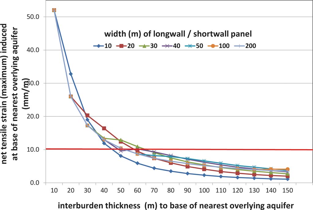
Figure 4 The relationship between longwall/shortwall panel width and the net tensile strain induced at the base of an overlying aquifer at varying heights above the workings.
The only known case where longwall mining was followed by pollution of an overlying aquifer occurred in the vicinity of Mainsforth Colliery in County Durham, where experimental work was undertaken by the National Coal Board to help establish the limits for prevention of water inrushes later proposed by Orchard (Reference Orchard1975). This work was undertaken during the last days of the colliery, when it no longer mattered if the workings became flooded. It included directly-mined connections into the overlying Magnesian Limestone aquifer, as well as longwall extraction within a few tens of metres of the base of the aquifer. Decades later, a plume of sulphate-rich water was indeed documented in the overlying aquifer (Neymeyer et al. Reference Neymeyer, Williams and Younger2007), reflecting the deliberate creation of hydraulic connectivity and the presence of a driving head from outcrop workings to the west (Kortas & Younger Reference Kortas and Younger2007). In all cases where the criteria set out by Orchard (Reference Orchard1975) and Singh & Atkins (Reference Singh and Atkins1983) were observed, and where mine water levels have fully recovered after the cessation of mining, there is no evidence of any pollution of the overlying aquifers via cross-strata flow.
5.4. Scale of stratal disruption: longwall versus shale gas fracking
It hardly needs stating that the scale of the deformation caused by even the most vigorous hydraulic fracturing procedure is orders of magnitude less than that caused by the progressive collapse of a 2 m-high mine void over an area of as much as 200,000 m2. Given the much more modest scale of stratal disruption caused by shale gas, and the greater depths beneath aquifers at which it is being proposed, application of coal mining standards of stand-off from aquifers can be expected to be extremely precautionary against any risk of direct inter-connection of fracked zones to aquifers or surface water bodies. For typical UK conditions, in which >1600 m of strata are expected to separate shale gas fracturing zones from the nearest overlying fresh water aquifers (see section 4.2.2), cursory inspection of Figure 4 reveals that the likelihood of creating a permeable hydraulic connection is negligible.
The only cases where 20th Century longwall workings are implicated in post-mining water pollution is where they are hydraulically inter-connected up-dip to much shallower workings which receive abundant recharge from rainfall on the Coal Measures outcrop area. Unfortunately, this condition applies to many of the coalfield areas of the UK. Yet there are a few cases of deep longwall workings beneath public supply aquifers where there is no up-dip connection to shallow old workings. Three prominent examples spring to mind: the Kent Coalfield in southeast England; the Point of Ayr Colliery in north Wales; and the Selby Coalfield in Yorkshire. Ironically, poor handling of saline mine water during the mining era led to extensive salinisation of the Chalk aquifer in Kent (Headworth et al. Reference Headworth, Puri and Rampling1980; Watson et al. Reference Watson, Burgess and Barker2012); this occurred because the saline water was simply dumped into unlined lagoons which leaked into the aquifer. Since closure of the last colliery (Betteshanger) in August 1989, water level recovery in the Kent Coalfield has reportedly been very slow (M. Parker pers. comm. 2010), and there is no sign of any outflow of polluted waters to the overlying Chalk aquifer – though admittedly it would be a little difficult to detect it where this is already polluted, due to the former lax brine disposal practices. The case of Point of Ayr is unusual for other reasons, and is briefly discussed at the end of section 6.4.5. A far more instructive case is the Selby Coalfield, which is now examined in some detail.
6. Selby Coalfield case study
6.1. Location and extent of the Selby Coalfield mining complex
The mining complex developed in the Selby Coalfield between 1976 and 2004 was, in many ways, the final jewel in the crown of the former UK National Coal Board (later renamed British Coal). When it was constructed, it was the world's largest underground coal mine, and it went on to be one of the most productive. Developed in response to the Middle East Oil Crisis of 1973, the development of the Selby Coalfield targeted long-suspected, but previously untouched, coal resources beneath the Vale of York (Fig. 5). There are as many as ten seams of potentially mineable thickness in the area, although the vulnerability to flooding of the low-lying Vale of York (it is only a few metres above sea-level) meant that only one seam could be worked throughout the area, with only localised possibilities of working, at most, one further seam (Eaton & Massey Reference Eaton and Massey1984). Thus, the fortunes of the Selby Coalfield were almost wholly predicated on the working of the Barnsley Seam beneath a total area of some 285 km2. Whilst the Barnsley Seam is widely worked elsewhere in South Yorkshire, the tract in the Selby area is entirely separated from much older coal workings to the west by truncation beneath the unconformable overstep of the basal Permian above the eroded core of a shallow anticline in the Coal Measures (Fig. 6).
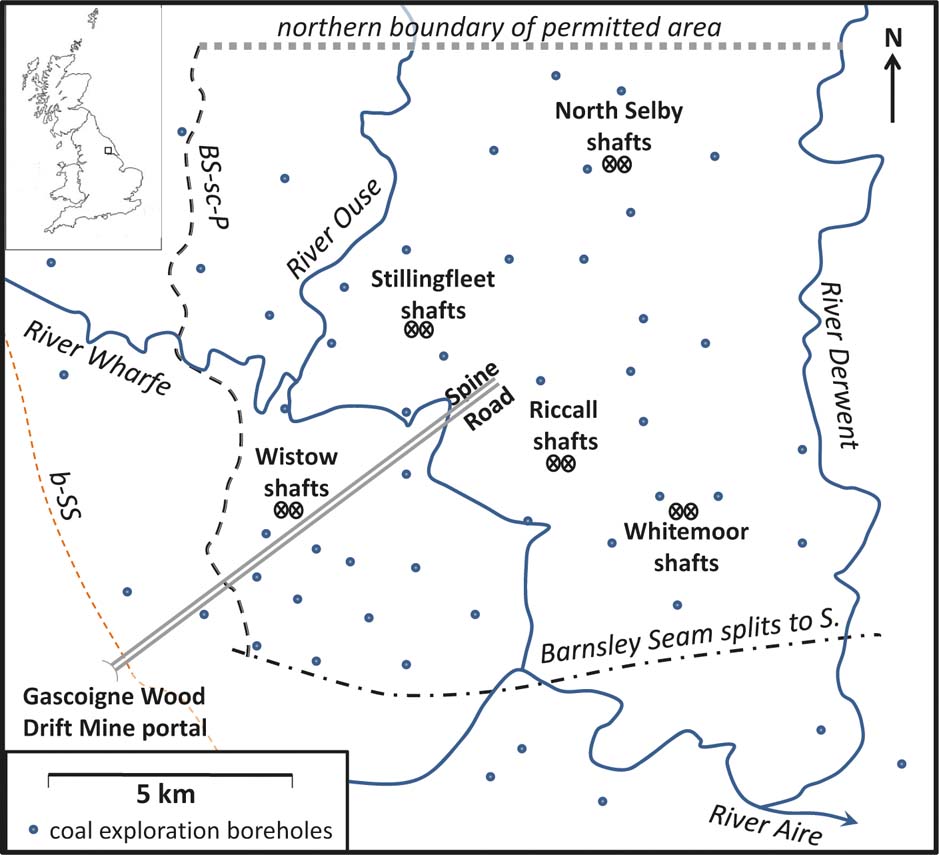
Figure 5 Location and simplified surface map of the Selby Coalfield, Yorkshire.
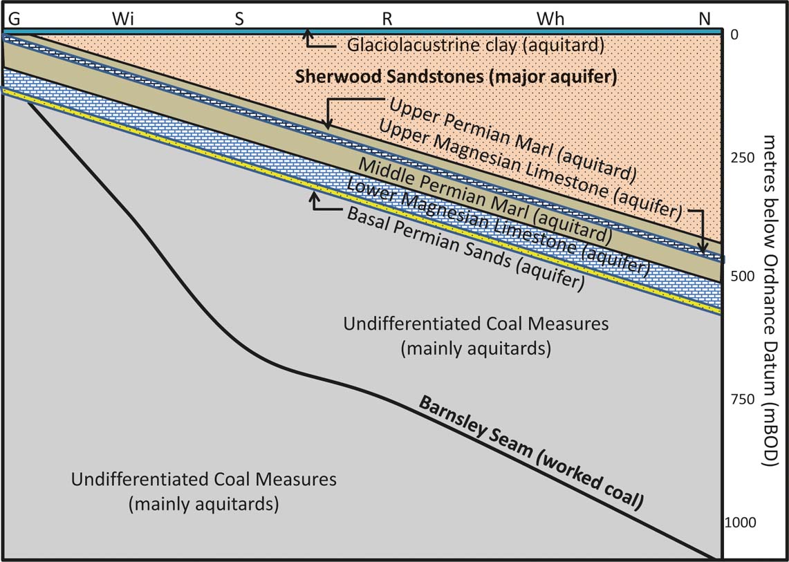
Figure 6 Synoptic W–E cross-section of the Selby Coalfield, Yorkshire, showing the approximate disposition of the main worked coal seam – the Barnsley Seam – in relation to overlying Permo–Triassic and Quaternary deposits. The abbreviations along the top axis show the approximate positions at which the various mines in the Coalfield (see Fig. 5) project onto the line of section as follows: G=Gascoigne Wood Drift portal; Wi=Wistow Mine; S=Stillingfleet Mine; R=Riccall Mine; Wh=Whitemoor Mine; N=North Selby Mine.
6.2. Hydrostratigraphy of the Selby area
The separation of the Selby Coalfield from the widely-interconnected old workings of the other Yorkshire coalfields means that it represents an entirely isolated hydrogeological system as regards hydraulic connectivity with other coal workings. However, in common with other recent mines further south (e.g., Kellingley, Hatfield and Maltby in Yorkshire; and Welbeck, Thoresby and Clipstone in Nottinghamshire), the Selby Coalfield is overlain by prolific aquifers of Permian and Triassic age (Fig. 6). Four distinct aquifer units are recognised (Eaton & Massey Reference Eaton and Massey1984), mutually separated by intervening aquitards of ‘marl’ (i.e., calcareous and anhydritic/gypsiferous mudstones). (It should be noted that the account which follows, and the labels in Figure 6, use the prevailing hydrostratigraphic terminology in this region (see Table 1 and Kortas & Younger Reference Kortas and Younger2013), which continues to favour older lithostratigraphic unit names because of the explicit mentions they make of aquifer-prone lithologies. An approximate correlation of these hydrostratigraphic unit names with the current lithostratigraphic unit names used by the British Geological Survey (Ford et al. Reference Ford, Cooper, Price, Gibson, Pharaoh and Kessler2008) is given in Table 1.)
Table 1 Approximate correlation of hydrostratigraphic unit names used in the text with the current lithostratigaphic units recognised by the British Geological Survey
The lowermost of the Permo–Triassic aquifers, immediately overlying the unconformable contact with the Coal Measures, is the Basal Permian Sands. This comprises poorly consolidated, well-sorted medium to coarse sands of aeolian origin, of highly variable thickness up to a maximum of about 20 m. One to two metres of marl aquitard separate the Basal Sands from the overlying Lower Magnesian Limestone (60–120 m thick), a sequence of dolomites and dolomitic limestones in which most ground water occurs in fractures, variably enlarged by dissolution. The enlargement of fractures, and thus the permeability, tends to increase westwards, towards the outcrop zone, reflecting greater dissolution in zones which have experienced sustained fresh water circulation. Much the same can be said of the far thinner Upper Magnesian Limestone (20–30 m thick), which is separated from the Lower Magnesian Limestone by up to 52 m of the Middle Permian Marl aquitard. A similar aquitard – the Upper Permian Marl (20–30 m thick) – overlies the Upper Magnesian Limestone, hydraulically separating it from the Sherwood Sandstones (Triassic). Overlying the entire Permo–Triassic sequence is a complex of grey, varved muds with subordinate fine sand horizons of Quaternary (Devensian) age. These sediments are formally termed the Heminbrough Glaciolacustrine Formation, and they are accepted as having accumulated in Glacial Lake Humber, which occupied most of the Vale of York until final melting of the ice-sheet which impounded it to the east around 10,000 years ago (Ford et al. Reference Ford, Cooper, Price, Gibson, Pharaoh and Kessler2008). They are generally between 15 m and 24 m thick and are predominantly of low permeability, except in the sand horizons; they therefore effectively confine the Permo–Triassic aquifers, except where these emerge from the clay mantle on what were islands in the ancient lake (Brown & Taylor Reference Brown and Taylor2006).
In the Selby Coalfield area, the Sherwood Sandstones contain abundant fresh ground water and are extensively pumped for both public water supply and industrial/agricultural purposes at numerous sites in the area (Brown & Taylor Reference Brown and Taylor2006). There are several sizeable industrial abstractions in the vicinity of Selby town (Dumpleton Reference Dumpleton and Younger2002). While the coalfield was operative, several of the mines operated shallow boreholes drilled into the Sherwood Sandstones to supply water for use both at surface (showers, canteen facilities, etc.) and underground (dust suppression and fire hydrants). These mine site abstractions were substantial; at Wistow, for instance, a peak abstraction rate of 909 m3/d was licensed. Hence, any degradation in the level or quality of ground water in the Sherwood Sandstones as a consequence of the mining operations would have directly prejudiced the mine's own activities. The mine managers therefore had a considerable interest in maintaining the good status of the aquifer.
Although the Magnesian Limestones yield significant quantities of fresh ground water outside the study area to the northwest (notably near Tadcaster, where the waters have long been used for brewing; Aldrick Reference Aldrick1978), in the Selby Coalfield area they invariably contain hard, sulphate-rich waters of impotable quality (Bottrell et al. Reference Bottrell, West, Yoshida, Barker and Tellam2006); this quality presumably reflects diffusional exchange of water from the enclosing Marls over geological time, indicating largely stagnant ground water flow conditions in the Permian aquifers in this vicinity.
As elsewhere in northern England and Scotland, the Coal Measures in the Selby area comprise cyclical sequences of mudstone, siltstone and sandstone, with sporadic seat-earths, coals and thin ironstone beds (Ford et al. Reference Ford, Cooper, Price, Gibson, Pharaoh and Kessler2008). As such, most of the Coal Measures strata are of low permeability and are regarded as aquitards. Occasionally, sandstones are thick enough to constitute notional aquifers, albeit their low interstitial permeability means that they yield modest quantities of water, which in this area is typically brackish. Together with their depth, these characteristics preclude them from the inventory of water resources; however, inflows from such sandstones could be a temporary nuisance during mining. The most prominent and laterally persistent of these sandstone aquifers is the Woolley Edge Rock, which is a complex of multi-lateral and multi-storey channel deposits, locally amounting to as much as 25 m in thickness (Ford et al. Reference Ford, Cooper, Price, Gibson, Pharaoh and Kessler2008). The Woolley Edge Rock was present in all of the Selby Shafts, and its position was carefully surveyed (Table 2). In the deepest shafts (North Selby), younger Coal Measures sandstones (the Brierley Rock, Ackworth Rock and Shafton Sandstone; Auld Reference Auld1989) also occurred, in close proximity to the unconformable contact with the overlying Basal Permian Sands – thus potentially extending the hydraulic influence of the latter locally. To avoid nuisance water ingress, these Coal Measures sandstones were carefully considered during shaft and mine planning.
Table 2 Summary of information on the five pairs of shafts at the individual mine sites in the Selby Coalfield. (Note that two shafts were sunk at each site, just a few tens of metres apart; the grid references given refer to a central point in each site).
Notes: Data collated from Auld (Reference Auld1989), Eaton & Massey (Reference Eaton and Massey1984), unpublished UK Coal reports and the author's own notes taken during shaft inspections in 2003.
a denotes estimated values where publicly-available records are insufficiently detailed.
b these are depths at the shafts. The median depth to the seam in the main bodies of workings in each of these mines is closer to: 300 m (Wistow); 700 m (Stillingfleet); 750 m (Riccall); 980 m (Whitemoor); and 1095 m (North Selby).
6.3. Brief overview of mining in the Selby complex
The Selby complex had an innovative design (Eaton & Massey Reference Eaton and Massey1984), albeit one derived from earlier developments in ‘horizon mining’ (Fritzsche & Potts Reference Fritzsche and Potts1954) in multi-seam workings elsewhere in northern England. Five distinct mines were developed in the Selby Coalfield (Figs 5, 7), each with a pair of shafts used for ventilation, haulage of materials and equipment, and workforce access (Table 2). However, no coal was brought to surface at these mines; rather, all production was transferred underground to hoppers which converged on a pair of parallel 15 km-long tunnels, collectively known as Gascoigne Wood Drift. The Drift was driven at a gradient of one-in-four from surface for 800 m, traversing the Lower Magnesian Limestone and Basal Permian Sands aquifers, before levelling out to continue some 14 km into the heart of the complex, at a horizon about 60–65 m below the base of the Barnsley Seam. The Drift tunnels housed conveyor belts which carried up to 2,000 tonnes of coal per hour through a maximum lift of 1000 m. As Eaton & Massey (Reference Eaton and Massey1984) commented, this was “equivalent [to] moving coal from Caernarvon to the top of Mount Snowdon”. The Drift delivered the run-of-mine coal to surface at an inconspicuous site, [SE 5280 3190], screened by the trees of Gascoigne Wood itself, where all coal processing and mine waste management was undertaken. As all coal produced from Selby was used in nearby power stations, preparation was in any case rather minimal, and waste deposits correspondingly modest.
Figure 7 Simplified summary mine plan of the Selby Coalfield, showing the areas in which coal was worked by shortwall, longwall and pillar-and-stall methods.
As they were never used for coal haulage, the five individual mine sites (Table 2; Fig. 7) were clean and quiet. Also, being well screened by trees planted on the landscaped bunds of the arisings from shaft sinking, uninformed passers-by who actually got a clear view of the mine buildings would be unlikely to identify the five sites as coal mines at all; they looked more like small factories, with the winding gear enclosed in towers which could have been taken for avant garde agricultural silos, in keeping with the surrounding rich arable farmland.
As the natural dip of the Coal Measures in this area is to the east (Fig. 6), the more eastern mines were also the deepest (Table 2). The shallower, western shafts (Wistow, Stillingfleet and Riccall) were the earliest to be completed (Wistow first, in 1979), and production began at these sites in 1983, while shaft completion and roadway development were still underway at the deeper North Selby and Whitemoor Mines further east. In the event, coal production in the complex had only been underway for less than two years when all production was halted by the 1984–85 national miners' strike. It was 1986 before all five mines were fully productive.
The original plans for the Selby complex as a whole envisaged a peak production rate of ten million tonnes per annum (Eaton & Massey Reference Eaton and Massey1984). In fact, the complex exceeded this aspiration, achieving 12 million tonnes in 1993/94; this accounted for more than 45 % of all UK coal production that year (Ford et al. Reference Ford, Cooper, Price, Gibson, Pharaoh and Kessler2008). However, average annual production was closer to 5.75 million tonnes. This disappointing performance in part reflected the loss of production during the miners' strike, but also reflected two geological issues:
(i) in the early days at Wistow Mine, some ground water ingress problems were encountered (see section 6.4.2), which were resolved by operating far narrower panels than had been envisaged;
(ii) although some 47 exploration boreholes were drilled and several 2D seismic surveys undertaken during mine planning, the pattern of faulting inferred from this information proved inadequate: “…Conventional 2D surface seismic surveying [had] determined the elements of the geological structure of the Selby coalfield [to comprise] large NE–SW trending faults of up to 130 m throw, together with large E–W-trending faults of up to 60 m throw. Faults with displacements down to 7 m [were] successfully identified in position and throw. As mining proceeded [however] a third element to the faulting was encountered. This comprised zones, up to 500 m wide and of some lateral extent with complex [extensional] and strike-slip faulting. The vertical displacement [on these features] is generally less than 5 m. These zones have been called "shear zones" and because of their irregular shape and extent [they] preclude mining over large areas …” (British Coal Corporation 1997).
Nevertheless, over the 21 years of production from 1983 until final closure of the coalfield (with the closure of Riccall Mine) on 26 October 2004, a total of 121 million tonnes of coal was extracted (Ford et al. Reference Ford, Cooper, Price, Gibson, Pharaoh and Kessler2008), which certainly places Selby amongst the more successful European mining complexes of comparable extent.
6.4. Hydrogeological experiences in the Selby Coalfield
6.4.1. Shaft sinking and drift-driving
Apart from the necessity of avoiding depletion or contamination of the ground water in the Permo–Triassic sequence, the developers of the Selby complex had to sink mine shafts through these highly permeable aquifers without flooding the incipient mine workings (Eaton & Massey Reference Eaton and Massey1984). To achieve this, the technique of ‘ground freezing’ was used. First developed in Germany in the closing years of the 19th Century, ground freezing involves drilling an array of deep boreholes around the circumference of a planned shaft and circulating a refrigerant (normally super-cooled brine) through them until the ground water in the vicinity has been frozen to form a cylinder of interstitial ice, which can simply be removed with the waste rock during shaft sinking. The frozen rock beyond the shaft perimeter serves as a temporary barrier to ground water ingress, allowing the shaft to be sunk dry through otherwise prolific aquifers. This technique was first used in the UK in the first few years of the 20th Century, to sink shafts through stratigraphically-equivalent strata in County Durham (Younger Reference Younger and Mather2004c).
Ground freezing was first used at Selby to facilitate construction of that part of the inclined tunnels of the Gascoigne Wood Drift which passed through the Basal Permian Sands Aquifer. This application of ground freezing to a one-in-four inclined tunnel was the first such use of the technique (Eaton & Massey Reference Eaton and Massey1984). Before the Basal Sands were reached, several other aquifers had to be traversed by the advancing tunnels. Fortunately, the prolific Sherwood Sandstones Aquifer crops out east of the Drift portal (Fig. 5) and was not cut by the tunnels. The modest quantities of ground water in sand horizons within the Hemingbrough Glaciolacustrine Formation were dealt with by conventional well-point dewatering, while water ingress from the Magnesian Limestone aquifers was dealt with by grout injection from boreholes drilled from the advancing drift. The inclined section of the Drift was sealed against the surrounding aquifers with segmented steel tubbing. The frozen section was thus restricted solely to the Basal Permian Sands Aquifer. This hybrid approach to ground water control during construction was highly successful: while uncontrolled inflow into the Drift tunnels from the surrounding aquifers would have been expected to exceed 757 L s–1 (Eaton & Massey Reference Eaton and Massey1984), the post-construction inflows to the Drift barely exceeded 1 L s–1. For instance, a pre-closure inspection of the Drift by the author on 6 May 2003 revealed that inflows from the Hemingbrough Glaciolacustrine Formation (which were captured in a former fan raise about 25 m from the portal) amounted to only 1.1 L s–1; the section of the drift passing through the Magnesian Limestones and Basal Sands was found to be dry, with the only hint of ground water ingress being the presence of small stalactite draperies along some of the joints in the steel tubbing between 492 m and 600 m in-bye (i.e., measured from the portal), which corresponds to the grouted section through the Lower Magnesian Limestone aquifer. Subsequent XRD analysis of the stalactites revealed them to be composed principally of calcite and dolomite, with minor gypsum and quartz. The calcite and quartz could be explained solely by interaction with the grout curtain; the dolomite and gypsum are more readily explained as products of evaporation to dryness of the hard, sulphate-rich ground water in the Lower Magnesian Limestone Aquifer. However, the quantities of water involved are negligible.
The sinking of the five pairs of vertical shafts in the Selby Coalfield (Figs 5, 7) involved the use of well fields around each shaft to circulate brine at temperatures of −20°C to −30°C. The end product in each case was a shaft with an internal diameter of 7.315 m, lined with 600–1400 mm of high-strength, high-durability, sulphate-resistant concrete (Auld 1989). As can be seen from the temporary freezing depths for the pairs of shafts listed in Table 2, the general strategy was to completely freeze the section of each shaft which passed through the Sherwood Sandstones, allowing an extra margin of 13–33 m into the Upper Permian Marl aquitard to ensure a good seal against the aquifer. Potential ground water inflows from deeper aquifers (in both the Permian and Coal Measures) were handled by a combination of grouting and pressure-relief wells drilled from within the deepening shaft (Hutchinson & Daw Reference Hutchinson and Daw1989). The concrete linings of the shafts were cast in situ behind temporary steel form-work (Auld Reference Auld1989). This meant that the heat released during curing of the concrete had to be allowed for in designing the width of the frozen annulus (Eaton & Massey Reference Eaton and Massey1984).
Only in the case of Wistow No. 1 shaft did the freezing target aquifers deeper than the Sherwood Sandstones; it was continued to below the base of the Permian. This reflected concerns that its closer proximity to the outcrop of the Magnesian Limestones might be reflected in higher permeabilities (see section 6.2). It was hoped that freezing of the Permian Aquifers around Wistow No. 1 shaft might also offer protection to the adjoining Wistow No. 2 shaft; however, this hope was betrayed by significant ingress from the Basal Permian Sands, requiring remedial grouting (Eaton & Massey Reference Eaton and Massey1984) and the installation of a steel ‘bandage’ against the zone of maximum inflow. In all other shafts, a combination of pressure-relief wells and grouting proved sufficient to handle all other inflows; indeed, the shaft sinkings at Stillingfleet and Whitemoor were to achieve UK speed records, at rates of up to 4.23 m per day (Eaton & Massey Reference Eaton and Massey1984). The high-strength, high-durability concrete shaft linings (Auld Reference Auld1989) proved highly effective, and pre-closure shaft inspections by the author at Stillingfleet, Riccall and Wistow on 17 April and 6 May 2003 revealed all shafts to be in excellent condition. Very minor seepages (0.01–0.5 L s–1) were observed at some of the interfaces between successive concrete pours, but shaft maintenance workers reported no significant changes in these minor water inflows over the preceding two decades. The larger inflows were captured by shaft garlands (shallow circumferential drains) and delivered to the shaft sumps. Lesser inflows often evaporated to dryness, leaving encrustations in the garlands and at the shaft-foot soffit. Whilst some of the shallower inflows produced ferric hydroxide precipitates, the deeper encrustations (e.g., from Stillingfleet No. 2 shaft-foot soffit) were later found by XRD analysis to be halite, reflecting evaporation to dryness of sodium chloride waters native to the Coal Measures strata.
6.4.2. Early lessons from coal production at Wistow
At the Wistow Mine shafts, the Woolley Edge Rock is absent, due to erosion prior to accumulation of the Permian succession, so that the closest aquifer to the coal workings is the Basal Permian Sands, lying about 115 m above the Barnsley Seam (Table 2). As this exceeds the maximum height of 105 m at which longwall-induced fracturing would be expected to result in a net tensile strain in excess of 10 mm/m at the base of (and thus water inflows from) the Permian aquifer, it was fair to assume that mining could proceed without fear of water inrushes. This did indeed prove to be the case east of the shaft. However, where panels were developed to the west (up-dip from the shaft), in an area known as Resource Block A, the angle of unconformity was such that the seam ended up being sufficiently close to the base of the Permian that this would fall within the proximal zone of extensional deformation of longwall faces (Fig. 3) worked to conventional widths (≤250 m). It is no longer clear how or why this was overlooked in the original mine planning. However, when the 120 m-wide face H02AW was worked in 1983, at about 80 m below the base of the Permian, the face had only retreated 275 m (out of an originally-planned total of 780 m), when goafing led to an inflow of up to 151 L s–1 L s–1 of ground water which had a high sulphate content, redolent of Permian affinities (cf. Bottrell et al. Reference Bottrell, West, Yoshida, Barker and Tellam2006). The rate of inflow declined steadily over the following week to around 37 L s–1, and subsequently declined to a residual flow which varied between 1.5 L s–1 and 3.8 L s–1 (Eaton & Massey Reference Eaton and Massey1984). This residual rate persisted; between 1997 and 2004, flow from the panel averaged 2 L s–1.
The initial inflow rate to the H02AW face was sufficient to prevent continued longwall working, forcing a radical reconsideration of the working methods for all of Resource Block A. This led to the development of ‘shortwall’ faces (30–60 m wide), each served by a single roadway along only one side of the panel (rather than the pair of flanking roadways used in longwall). The shortwall approach was adopted for almost all of the Wistow workings (south)west of the shafts (Fig. 7), except for a small area in the extreme southwest, where a non-caving method of mining was adopted (stoop-and-room working with a road-header machine). The reduction in panel widths from 120 m to as little as 30 m dramatically reduced the strain in the overburden (cf. Fig. 3), and thus the rate of ground water inflow. Further down-dip, panel widths were gradually widened again and conventional double-entry longwall faces re-established. Occasional surprises disrupted progress, such as on face H706, where heavy inflow brought a premature halt to production after 150 m of face retreat. This might reflect an unanticipated depression in the palaeotopography at the base of the Permian. However, after lessons from H02AW and H706 had been learned, the vast majority of faces throughout the Selby complex were worked by conventional longwall techniques, with any water ingress being limited to minor, ‘nuisance’ quantities. Hydrochemical evidence (i.e., a predominance of chloride over sulphate as the dominant anion) generally indicated that most face water originated within the immediate Coal Measures overburden, rather than from the distant overlying Permian.
The temporal pattern of inflows to the Wistow panels merits comment. Without exception, initially high inflow rates to panels (here and in all other UK coalfields) declined exponentially after their initial onset, typically by two orders of magnitude. This likely represents two processes: Darcian drainage of discrete aquifers, so that a declining head in the source zone results in a reduction in flow rate; and a ‘self-healing’ process in which erosion of silt- and clay-rich strata yields fine sediment which can then clog the fracture flow paths leading to the underlying coal face. Thus, despite the very high initial ‘water make’ of 151 L s–1 on the H02AW face in 1983, when the author investigated ground water occurrence at Wistow Mine two decades later as part of closure planning, residual flow from the entire mine was only 5.4 L s–1 (Table 3).
Table 3 Quantities of water encountered in the then-working mines of the Selby complex in 2003
Notes: Data provided by managers of individual mines, calculated from logged run-times and rated capacities of pumps used either to transfer the water within the mine (where disposed to deeper workings), or to discharge them to surface (see comments for individual mines for further clarification).
6.4.3. Deep and dry: Riccall, Stillingfleet, Whitemoor and North Selby
In the mines to the south and east of Wistow, the interburden interval from the Barnsley Seam to the Permian aquifers ranged from 315 m (at Stillingfleet) to 515 m (at North Selby) (Table 2); and thus conventional longwall mining with faces up to 240 m wide could be undertaken with virtually no risk of establishing hydraulic connections with the Permian (cf. Fig. 3).
In the deeper Selby workings, minor sandstone aquifers also occur within the Coal Measures; the closest of these to the Barnsley Seam is the Woolley Edge Rock, with three higher sandstones also being logged at North Selby and Whitemoor (see section 6.2). However, with a typical interburden interval between the Barnsley Seam and the Woolley Edge Rock of 127 m or so, there was virtually no risk of longwall workings in the Barnsley Seam inducing inflows from these Coal Measures sandstones either, and so it proved (Table 3).
In only one small area of the Selby complex was mining undertaken any closer to these aquifers: this was in the Stanley Main Coal Seam at Riccall (Fig. 7), which is about 70 m above the Barnsley Seam. The Stanley Main was only worked in the latter years of mining at Riccall, after the completion of longwall panels in the underlying Barnsley Seam. When the Stanley Main panels began to goaf, inflows to these five faces totalled up to 30 L s–1; albeit they rapidly declined to around 3 L s–1 (thus reflecting the general pattern of ‘self-healing’ of induced inflows discussed in section 6.4.2). There were two possible sources for these inflows to the Stanley Main workings: induced inflows from the Woolley Edge Rock (which is only about 57 m above the Stanley Main at Riccall, and thus well within its proximal zone of extensional deformation; Fig. 3); and/or from accumulations of water in bed-separation hollows in Coal Measures strata beneath the Woolley Edge Rock, which would have developed during the previous goafing of the longwall workings in the underlying Barnsley Seam (the proximal extensional zone of which would be expected to extend about 48 m above the base of the Stanley Main Seam). These Stanley Main inflows were responsible for a temporary increase in inflow rates to Riccall in the year prior to closure, so that the total inflow for that mine of 9 L s–1 recorded in Table 3 was elevated above the prior steady rate from both Whitemoor and Riccall of only 6 L s–1.
6.4.4. Hydrogeology of the Sherwood Sandstones above the Selby coalfield workings
As noted in section 6.2, the Sherwood Sandstones constitute a major public-supply aquifer throughout the Vale of York, and the aquifer is widely and heavily exploited in the area underlain by the Selby coalfield complex (Brown & Taylor Reference Brown and Taylor2006). Monitoring of ground water in the aquifer has expanded in phases since the 1960s, and an extensive network of observation boreholes now exists throughout the area to allow the Environment Agency (EA) to continually appraise the status of the aquifer. Furthermore, the EA analyses water samples from the majority of abstraction wells in the district, including those pertaining to the mines, when these were operative. These show the Sherwood Sandstones to contain fresh ground water of Ca–HCO3 facies with moderate hardness, although salinity and hardness both increase with depth and down-dip, in parts of the aquifer that do not participate in active circulation to rivers and pumping wells.
As part of a nationwide strategy to characterise ground water resources, numerical models of regional ground water flow were developed for most aquifers in England by the Environment Agency in the 1990s and 2000s (Shepley et al. Reference Shepley, Whiteman, Hulme and Grout2012). Amongst these regional models was one for the Sherwood Sandstones in the Selby area (Brown & Taylor Reference Brown and Taylor2006). This model was developed by expert ground water modellers using the entire hydrogeological database available for the aquifer. One of their principal tasks was to quantify all fluxes of water into and out of the aquifer. The ground water budget for the Sherwood Sandstones for the simulation period 1960–2003 is explained by an almost complete cessation of natural discharge via springs and leakage to rivers by around 1970, with well abstractions becoming the overwhelmingly dominant form of ground water discharge from the aquifer, at around 925 L s–1 (∼80 megalitres per day) across the Selby area. This has been balanced by a degree of depletion of long-term storage (represented by water table drawdown) augmented by:
(i) increased capture of rain-fed recharge in outcrop areas;
(ii) head-dependent leakage from the sand horizons within the Quaternary sediments; and
(iii) induced leakage from rivers.
The model results indicate that, in the 1960s and 1970s, sources (i) and (ii) predominated, accounting for around two-thirds and one-third respectively of the water pumped from the aquifer. By the mid-1980s, source (iii) was also becoming significant; and by 2003, sources (i) and (ii) were each contributing two-fifths of the total yield, with the final fifth coming from source (iii) (Brown & Taylor Reference Brown and Taylor2006).
In developing this ground water budget, Brown & Taylor (Reference Brown and Taylor2006) considered the possibility of loss of water from the Sherwood Sandstones Aquifer by downward leakage (via the underlying Magnesian Limestones; Fig. 6) to the underlying coal workings. No evidence for any such leakage was found. The head in the Magnesian Limestones would have had to be less than in the Sherwood Sandstones for this to be possible, and with the depressed water table in the latter due to well-pumping, the opposite was in fact the case. The (hydraulically implausible) notion that leakage might somehow bypass this dominant head system by short-circuiting via discrete faults was also considered, but Brown & Taylor (Reference Brown and Taylor2006) concluded that “… there is no indication at present that mining has had any impact on faulting resulting in potential connection between the Sherwood Sandstone and underlying Permian aquifers …” Indeed, examination of the gross water quantities involved tells its own story: even if every drop of the 19 L s–1 of water encountered in the mine workings (Table 3) were somehow sourced from the Sherwood Sandstones (in defiance of all available piezometric and hydrogeochemical evidence!), then this would still amount to only 19/925=2 % of the water flowing through the Sherwood Sandstones in this district, which is well within the bounds of error of the aquifer flow rate estimates.
The only detected impact of the coalfield operations on the aquifer was arguably beneficial: repeated time-drawdown analysis of intermittent pumping wells near Selby revealed that the working of Wistow Mine longwall panels H93 and H94 led to localised increases in the transmissivity in the Sherwood Sandstones Aquifer (Dumpleton Reference Dumpleton and Younger2002). Much of the increase in transmissivity was transient, however, reflecting an initial extensional widening of joints in the aquifer as the distal extensional zone above the panels passed into it, followed by partial re-closure of the joints after mining subsidence ceased. It is crucial to note that faces H93 and H94 experienced no unusual inflow during the period of transmissivity change in the Sherwood Sandstones, because the compressional zone above the faces (Fig. 3) was always developed below the base of the Permo–Triassic aquifers. This illustrates that propagation of deformational pulses is not synonymous with establishment of hydraulic continuity. In terms of the behaviour of the Sherwood Sandstones themselves, Brown & Talyor (Reference Brown and Taylor2006) comment “… these changes [in transmissivity] are not considered significant in terms of a large scale ground water resource model.”
It remains the unanimous view of ground water managers in the region (A. Lancaster (Environment Agency) and L. Wyatt (Coal Authority) pers. comms May 2015) that the quality and quantity of ground water in the Sherwood Sandstones Aquifer have, to date, been unaffected by the 21 years of large-scale mining in the underlying Coal Measures. However, it is prudent to enquire whether there is any risk that this happy state of affairs might change in future.
6.4.5. Water issues post-closure
Given the prior history of mine water pollution in the UK in the decade prior to the closure of Selby (see, for instance, Parker Reference Parker2003) there was understandable anxiety that the closure of the Selby Coalfield might lead to pollution of the overlying freshwater aquifers (cf. Neymeyer et al. Reference Neymeyer, Williams and Younger2007), or even of adjoining rivers (cf. Parker Reference Parker2003), which in this case would be the Rivers Ouse and Derwent (Fig. 5). Since the closure of Selby came after the implementation of the Mines (Notice of Abandonment) Regulations 1998, the mine owner had an obligation to evaluate and report formally to the Environment Agency on these potential pollution risks, in terms of quantity, timing and quality. The present author was intimately involved in independent observational verification of key points in that report, and in critically reviewing all of its contents.
Table 3 summarises the quantities of water being handled in the Selby complex in the year leading up to final closure, calculated from logged run-times and rated capacities of pumps. It should be noted that, because pumps seldom maintain ‘nameplate’ capacities once used regularly in a coal mine, these figures will overestimate the true flow rates, perhaps by as much as 15 % (cf. Younger et al. Reference Younger, Banwart and Hedin2002). Even so, the total ‘water make’ of around 19 L s–1 is extremely modest compared with coalfield areas of similar size where direct connections exist up-dip via old workings to surface recharge zones. Examples include 300 L s–1 from the Kibblesworth Shaft in the northwestern Durham Coalfield (Younger & Henderson Reference Younger and Henderson2014); 124 L s–1 from Bates Shaft, eastern Northumberland Coalfield (L. Wyatt (Coal Authority) pers. comm. 2013); 120 L s–1 from Frances Colliery, Dysart, Fife; and 75 L s–1 from Polkemmet Shaft, West Lothian (Parker Reference Parker2003).
The time variance of inflows to the Selby workings indicates that the vast bulk of this 19 L s–1 represented localised depletion of ground water storage within the Coal Measures sandstones and (in the shallowest workings of Wistow) into the basal Permian. As noted in section 6.4.3, an invariable pattern was observed in which relatively high inflows rapidly declined to very minor rates over a period of weeks; this is consistent with one-off drainage of isolated zones of ground water storage. Were there any direct hydraulic connections to shallower, more permeable aquifers, no such decline would be experienced. Such was the case, for instance, with the Westfield Opencast coal site in Fife, where very high inflows from a prolific Devonian sandstone aquifer via the East Ochil Fault were sustained throughout the working life of the pit, declining only when the void was finally left to flood and the head gradient across the fault was gradually reduced (Younger Reference Younger, Loredo and Pendás2005).
Of course, even small amounts of water coming from slow drainage of storage are also susceptible to eventual cessation when head gradients reverse. This has been the invariable experience during coalfield abandonment throughout the UK (Younger et al. Reference Younger, Banwart and Hedin2002; Parker Reference Parker2003). Even where there is hydraulic connectivity back to surface recharge zones, 40– 60 % of the inflow rates during mining prove to have been head-dependent, and are therefore eliminated from the water budget as the workings flood. In the case of Selby, then, without any site-specific analysis, the residual rate of water flow through the workings after recovery would be very low; simple application of the ratios observed elsewhere would suggest that it would not exceed 11.5 L s–1. However, given the complete absence of any hydraulic connection from the Selby mine workings to shallow old workings at higher elevations to the west, and given the low relief of the Vale of York itself, no driving head is likely to exist after rebound, and thus the residual water flow rate will be zero.
Absolute a priori quantification of the decline in inflow rate is usually hindered by a lack of direct measurements of the piezometric heads in the source zones feeding water into the mine workings (Younger & Adams Reference Younger and Adams1999), and this is also largely the case at Selby. However, two snippets of relevant information are available from this coalfield. First is the minor inflow (1.1 L s–1) of water from the Quaternary Hemingbrough Glacio-lacustrine Formation to the Gascoigne Wood Drifts at about 1 m AOD. However, as the Drifts were backfilled and grouted beyond that point of inflow at the time of closure, it is likely that this component of inflow has already been eliminated. The second snippet relates to experience during shaft sinking at North Selby (Eaton & Massey Reference Eaton and Massey1984), when the Ackworth Rock (a sandstone in the Coal Measures) at 526 m depth yielded ground water with a measured pressure of 5.17 MPa – which is hydrostatic (i.e., corresponds to a column of water extending to the surface). Presumably, this reflects lateral hydraulic continuity within the Ackworth Rock, up-dip to its sub-crop against the Permian, and then hydraulic continuity within the Permian back to the surface, where head is ultimately controlled by outflow to local rivers (Aldrick Reference Aldrick1978). Although similar hydrostatic pressures were not encountered deeper than 690 m in any of the Selby shafts (Auld Reference Auld1989), this observation suggests that at least some of the water entering the old Selby workings might not cease to flow into the workings until hydrostatic conditions have been restored. How long might this take?
Estimation of rates of mine water ‘rebound’ (i.e., recovery to a static ground water level) can be a complex task (Adams & Younger Reference Adams and Younger2001), and a complete analysis is beyond the scope of this paper. There are two components to consider:
(i) the physical flooding of empty mine voids (essentially up to the point that the roadway connection (‘inset’) to the shallowest shaft becomes flooded, which in this case is at Wistow; Table 1); and then
(ii) the increase in storage as water levels continue to rise and the accumulated water in the voids is put under increased pressure. In this second phase, the principal control on the volume entering storage is no longer the void volume, but rather the compressibility of the goaf and fractured strata overlying the worked panels.
A simple first approximation for (i) can be made by estimating the total void volume created by the mining, and then comparing this with the known water inflow rate. This will give a minimum time for flooding of all voids to the foot of the shallowest shaft (Wistow). Once all of the voids are flooded, however, further water level recovery will continue – manifest in the rise of water levels within the shafts. As a total of 121 million tonnes of coal was mined at Selby, and this had an average density of 1.3 tonnes per cubic metre, the total voidage created over the life of the complex was around 93 million cubic metres (Mm3). However, around a third of the former panels had already been flooded before the cessation of mining in 2004, so that the remaining voidage is on the order of 62 Mm3 (note that, as indicated in Figure 3, this void space will have been redistributed between the goaf and the overlying strata in the proximal extensional zone). Given an annual inflow rate of 602,338 m3 (=19.1 L s–1), the completion of phase (i) would be expected to take 102 years. Even if it is argued that unusual degrees of compaction of the Selby goaf might render much of the void space inaccessible, estimates for phase (i) would still be on the order of several decades; for instance, even assuming a 90 % loss of void space, phase (i) would still require 15 years.
As regards phase (ii), given the invariably low values of confined storativity (typically 10–3 or less, even for heavily fractured aquifers; Younger Reference Younger1993), then even for the undiminished inflow rate of 19.1 L s–1 (which equates to around 0.013 m equivalent depth of water inflow per year over the ∼4,600 hectares of worked panels at Selby), the further head rise of 378 m (from the Barnsley Seam inset at Wistow; Table 2) which would be required to complete phase (ii) would only be expected to take around three years. Phase (ii) is thus of negligible duration compared to phase (i).
Evidence to date, 11 years after mine closure, corroborates the above analysis. At present, methane is extracted (for use in electricity generation) from the mine complex at Stillingfleet, and gas pressures are also monitored at the Riccall and Wistow shafts. Gas pressures have remained equal in all three pairs of shafts since closure (S. Hockley (Harworth Estates) pers. comm. 2015). This indicates that water levels have not yet reached the base of any of the shafts; had this occurred, the gas pressure at the affected shaft would deviate from that in the others. (As Riccall is the deepest, this effect would be expected there first.) Indeed, once the shaft insets are all flooded, methane delivery will cease, and that economic activity will come to an end (Jardine et al. Reference Jardine, Boardman, Osman, Vowles, Palmer, Jardine, Boardman, Osman, Vowles and Palmer2009); flooding of mine roadways has long been known to prevent any further methane release (Younger Reference Younger2014b). From that point onward, the shafts will only be useful for hydrogeological purposes.
The simple approach to mine water rebound estimation used above does not incorporate the gradual decline in inflow rates as the head gradient between the flooded workings and the ground water source zones decreases. If this effect is added to the analysis, all timescales will become significantly extended. Neither does the above approach account for the fact that both flooding of voids and pressuring-up of the aquifer will occur simultaneously in different parts of the mine system. Whatever the precise dynamics, however, it is clear that the minimum timescale for total recovery of water levels in the Selby complex is in the order of several decades. It is important to note that, as the highest head measured in the Selby workings was hydrostatic in relation to the overlying ground surface, there is no evidence of any potential for development of a sufficiently greater head in the deep workings to drive polluted water either up through the overlying strata (even if the permeability permitted) or through any flaws in the concrete linings of shafts. As has already been noted (section 6.4.4) the total inflow to the mine workings prior to closure equates to just 2 % of the flow through the Sherwood Sandstones in this area, so even wholesale evacuation of mine water to the Sherwood Sandstones could have only localised effects, which would soon be arrested by natural attenuation within this permeable and dynamic aquifer.
However, even in the absence of sufficient driving head, mine water contaminants could, in theory, diffuse into surrounding fresh ground water if there were sufficient effective (i.e., interconnected) porosity through the concrete liners. As noted in section 6.4.1, the author undertook detailed independent inspections of the six remaining mine shafts in the Selby Coalfield in Spring 2003, a year before final closure, and they were found to be in excellent condition, with no indication of any physical deterioration or seepage where they pass through the Sherwood Sandstones and Permian aquifers. Given the thicknesses of sound concrete lining these shafts (Auld Reference Auld1989), diffusional movement of contaminants seems highly unlikely. It is difficult to envisage what weathering process would change this situation, in a quiescent subsurface setting isolated from the weather. Yet what if some degree of leakage or diffusion did eventually occur? How polluted would the water be?
Table 4 summarises the principal chemical characteristics of the waters encountered in the three mines which were still working in 2003, in the run-up to final closure. It is striking how similar these are to typical flow-back fluids (see section 4.2.1), being predominantly Na–Cl brines). Iron – which is the most common individual contaminant in mine waters – is present at elevated concentrations, though these are actually very modest compared to most polluting mine waters in the UK (cf. Parker Reference Parker2003). Flooding of the workings would be expected to lead to a further increase in iron and sulphate concentrations and a decrease in pH as efflorescent pyrite weathering products dissolve (Younger Reference Younger and Nicholson1998, Reference Younger, Gieré and Stille2004b; Younger et al. Reference Younger, Banwart and Hedin2002). Given the low-sulphur status of the Barnsley Seam (Eaton & Massey Reference Eaton and Massey1984), however, high iron concentrations (>20 mg L–1) and an acidic pH (<6) would not be anticipated in this setting (Younger Reference Younger2001). As sulphate concentrations are already close to the saturation limit for gypsum (∼2500 mg L–1), there is little scope for further increase in dissolved sulphate. However, given that the drinking water limit for sulphate is 250 mg L–1, a little water with these sorts of sulphate concentrations can contaminate ten times the volume of any fresh water it mixes with (Neymeyer et al. Reference Neymeyer, Williams and Younger2007). Indeed, the overall mineralisation of the Selby mine waters would be the prime concern, given how far their dissolved load exceeds that of the local fresh ground water in the Sherwood Sandstones (listed for comparison in Table 4). But would the water at the top of the recovered water column in the mine shafts be as saline as the waters listed in Table 4? In the Table, the mines are listed in order of increasing depth (cf. Table 2). It is immediately evident that total mineralisation (represented by conductivity) increases with depth, something commonly observed throughout UK coalfields (e.g., Younger Reference Younger and Nicholson1998) and, indeed, in other coalfields and natural aquifers worldwide (e.g., Younger Reference Younger2007). Water sourced from shallow sources (e.g., rainfall or leakage from rivers) tends to be of low ionic strength. Because such fresh water is less dense than saline water, it has a tendency to ‘pool’ above the saline water. Hence, where deep mine workings are hydraulically continuous with shallower workings, we see pronounced stratification of the water columns in abandoned mine shafts (Nuttall & Younger Reference Nuttall and Younger2004). It is simply not reasonable to postulate undiminished inflow of water right up to the level of shallow aquifers and persistence of high levels of salinity at the top of the mine water column. So even in the unlikely event that a small amount of mine water were to enter the Sherwood Sandstones, it would not be anything like as saline as the mine waters listed in Table 4.
Table 4 Summary of principal chemical characteristics of waters encountered in Selby mine workings in 2003; with median values for the overlying public supply aquifer (Sherwood Sandstones) for comparison
Notes: Analyses of mine waters undertaken by TES Bretby Ltd on behalf of UK Coal (Mining) Ltd. The waters were sampled monthly and showed no variation in composition beyond the limits of instrumental accuracy.
Values for Sherwood Sandstones are median reported values from the baseline survey of ground water chemistry in the Vale of York by Shand et al. (Reference Shand, Tyler-Whittle, Morton, Simpson, Lawrence, Pacey and Hargreaves2002).
a original paper record unclear, so value not certain; but consistent with conductivity and electro-neutrality balance of other dissolved equivalents.
b recalculated from value reported by Shand et al. (Reference Shand, Tyler-Whittle, Morton, Simpson, Lawrence, Pacey and Hargreaves2002) as mg HCO3– /L.
To summarise the post-closure water issues at Selby:
• There is a lack of hydraulic connection between the Sherwood Sandstones and the Coal Measures (Brown & Taylor Reference Brown and Taylor2006).
• The total ‘water make’ of the Selby Coalfield at the time of closure in 2004 was 19.1 L s–1, which is equivalent to only 2 % of the flow occurring through the overlying Sherwood Sandstones aquifer.
• Recovery of water levels is likely to take many decades, and perhaps more than a century, and the rate of water inflow into the workings over that time period will gradually decline as head gradients decrease, tending towards zero at completion of rebound.
• The principal water quality concern would simply relate to salinity; although (unlike in cases where the mine workings are connected up-dip to shallow old workings receiving direct rainfall recharge; e.g., Neymeyer et al. Reference Neymeyer, Williams and Younger2007), the maximum quantities of water that could feasibly be involved at Selby would be insufficient to give rise to widespread aquifer pollution.
• Methane will only be available to be captured from the remaining shafts for commercial use until the bases of the shafts are all submerged by rising mine water; although, as indicated, this will not come to pass for many years yet.
The last point is important, as the site owners are legally obliged to monitor for mine gases for as long as the shafts are emitting them; where little or no methane is anticipated, the mine gases have no value and thus monitoring is simply a nuisance. In such cases, awaiting a century-long natural rebound process is unattractive. For instance, at Point of Ayr Colliery in North Wales, which had a similarly low water make (5.4 L s–1) to that at Selby, but uneconomically low methane concentrations in the post-closure mine gas stream, the mine owners reached agreement with the Environment Agency to deliberately flood the mine with sea water to seal all nuisance gas deep below ground forever beneath a high head of water (Younger et al. Reference Younger, Jenkins, Rees, Robinson, Jarvis, Ralph, Johnston, Coulton, Nichol, Bassett and Deisler2004).
6.5. Lessons from Selby for shale gas developments
What can these experiences tell us about the likely hydrogeological impacts of shale gas developments in Carboniferous strata in northern England and Scotland? There are several clear lessons:
• In the case of Selby (Fig. 6), unlike in Scotland (Fig. 2), the zone of artificial fracturing is directly overlain by one of the most permeable and heavily-used aquifers in the country. Selby is, therefore, a more severe test for such activities than any shale gas site in Scotland (and, indeed, in most of northern England) would ever be.
• Extensive artificial fracturing of the subsurface, on a scale far larger than could ever be achieved by ‘fracking’, and at depths far shallower (e.g., 378 m at Wistow, versus >2,000 m for most northern UK shale prospects) did not result in the development of any hydraulic connectivity to overlying fresh water aquifers or surface waters (see section 6.4.4). This lack of hydraulic connectivity was abundantly evidenced by monitoring of inflows to the mines, mine water chemistry, aquifer piezometry and extensive modelling of ground water flow in the overlying aquifer.
• Even where deformation above caving longwall panels led to an increase in fracture permeability in the Sherwood Sandstones aquifer (Dumpleton Reference Dumpleton and Younger2002), no hydraulic continuity between this aquifer and the mine workings was ever established (see section 6.4.4). All of this suggests that the far less energetic process of fracking, undertaken at far greater depths, has essentially no chance of giving rise to hydraulic connectivity to shallow aquifers by means of induced fractures.
• Although the Selby Coalfield is extensively faulted, to a degree which hindered original extraction plans (see section 6.3), at no point during the working of the mine did intersection of faults lead to significant increases in water ingress. This is not surprising, as the faults are oriented approximately normal to the present-day azimuth of maximum compressive stress. Clearly, the mere presence of faults does not mean that hydraulic continuity will be established; contrary to the claims made (e.g., Smythe Reference Smythe2014a, Reference Smytheb, Reference Smythec) in recent shale gas and coalbed methane planning hearings in Scotland.
• When implementation of the initial mine design at Wistow induced inflows from nearby minor aquifers (Coal Measures sandstones and/or the base of the Permian), the extractive activity had to be halted (see section 6.4.2). Similarly, any shale gas fracking operation which connected into an overlying aquifer would be flooded, and the costs of pumping the well out (which is essential for gas to flow) would become prohibitively expensive, if not even physically impossible, given the constraints of borehole diameters (since the achievable rate of pumping correlates with pump diameter).
• Although the mine waters encountered at Selby (Table 4) were very similar to the flow-back fluids which arise in shale gas operations (see section 4.2.1), it proved straightforward to handle them, either by long-term disposal into old workings down-dip, or by pumping and disposal to tidal waters via pipelines (Table 3). This was handled without any problems, under essentially the same regulatory regime as is currently in force in the UK. There is no reason to suppose that this regime will find it any more difficult to cope with shale gas flow-back fluids.
• The notion that disused gas wells will inevitably leak methane to the atmosphere, with the attendant implications for human safety and the greenhouse effect, is inconsistent with the physics of under-pressured gas reservoirs, such as abandoned mine workings or depleted shale gas zones. Even a modest water head above a methane-producing zone in a coal mine tends to eliminate methane emissions, as operators of abandoned mine methane power plants will attest (see section 6.4.5). In any case, under UK regulations, disused gas wells must be completely backfilled and sealed with cement-based grouts (Thorogood & Younger Reference Thorogood and Younger2015).
• The excellent condition of the concrete linings in the Selby shafts after more than thirty years of intensive use (see section 6.4.1) provides a good worked example of the durability of cylindrical, cement-based structures in the subsurface. This helps offer some perspective on the concerns over long-term integrity of casing cement installations in shale gas wells.
7. Conclusions
This investigation has brought a wealth of experience in the hydrogeology of UK deep coal mining to bear on the present-day concerns around potential shale gas (and coalbed methane) developments. The overall lesson is clear: there are no prima facie geomechanical, hydrogeological or geochemical reasons why unconventional gas resources in northern England and Scotland could not be developed without causing aquifer pollution.
That does not mean, of course, that unconventional gas resources should be developed. There are many wider issues to consider in reaching a decision on that, including climate change commitments, security of energy supply, and importing resources from countries with poorer environmental and human rights records than our own, while leaving our own resources untouched. These matters have recently been evaluated in great detail by a panel of the Royal Society of Edinburgh (2015) and are not discussed further here. If we decide not to develop our unconventional gas resources, however, we ought to do so for valid reasons; the long experience of industrial development in the UK Carboniferous sequence suggests that fear of aquifer pollution is not one of them.
8. Acknowledgements
Much of the work reported here was undertaken by the author in 2003 for the former UK Coal (Mining) Ltd. The author is very grateful to former employees of that company, in particular Ted Watkins and Martin Brumby, for their practical assistance with the underground work and data sourcing. Much of the wider mine water research drawn upon here was funded by the Natural Environment Research Council (NER/A/S/2000/00249) and the Engineering and Physical Sciences Research Council (GR/S07247/01; GR/R73522/01 and GR/L55421/01). The author is particularly grateful to several colleagues for suggesting useful literature on shale gas and for stimulating discussions, especially: Dr Rob Westaway, Dr Alistair McCay and Dr Neil Burnside (all at the University of Glasgow); Professor Rebecca Lunn and Professor Zoe Shipton (University of Strathclyde); Andrew Gunning (RSKW Ltd); members of the research consortium of the Horizon 2020 research project ‘SHEER’ (SHale gas Exploration and Exploitation induced Risks; EU project no. 640896; www.sheerproject.eu); and members of the joint Royal Society/Royal Academy of Engineering Panel on Shale Gas Fracking (Mair et al Reference Mair, Bickle, Goodman, Koppelman, Roberts, Selley, Shipton, Thomas, Walker, Woods and Younger2012) and of the Scottish Government Expert Panel on Unconventional Gas (Masters et al. Reference Masters, Shipton, Gatliff, Haszeldine, Sorbie, Stuart, Waldron, Younger and Curran2014), on both of which the author served.
NB: In the interests of transparency, although the author was formerly a founder-Director of a company (Five-Quarter) that was attempting to pioneer a novel approach to in situ coal gasification coupled to carbon capture and storage deep beneath the North Sea, he has had no involvement at all with any shale gas or coalbed methane companies. All interpretations and opinions expressed in this paper are the sole responsibility of the author and are not to be construed as representing the views of any organisations named herein.


 Open access