


I. INTRODUCTION
Selective laser melting (SLM) is one of the powder-based additive manufacturing techniques used to produce three dimensional near-net shaped components with superior properties layer by layer. Reference Attar, Prashanth, Chaubey, Calin, Zhang, Scudino and Eckert1–Reference Bremen, Meiners and Diatlov4 As the name suggests, a laser source(s) is used to melt the powder layers selectively as dictated by a computer model (generally a computer aided design—CAD file or a computed tomogram—3D CT scan). The SLM process offers a high degree of freedom and theoretically parts with any geometry (complex shapes and structures) and can be produced without restrictions, which are otherwise difficult or nearly impossible to produce using conventional manufacturing processes. Reference Sercombe and Schaffer5–Reference Löber, Schimansky, Kühn, Pyczak and Eckert8 This process is also believed to lower the production time of complex parts, to maximize material utilization, and is considered to be environmentally friendly. Reference Olakanmi, Cochrane and Dalgarno9
Most of the SLM research is focused on the following alloys: (i) pure iron, stainless steel, and different tool steel grades in the directions of parameter optimization, structure optimization, and evaluation of mechanical properties Reference Ma, Wang, Gao and Zeng10–Reference Zhang, Dembinski and Coddet13 ; (ii) Al-based alloys, like Al–12Si and AlSi10Mg, mainly focused on parameter optimization and evaluation of various properties Reference Prashanth, Scudino, Klauss, Surreddi, Löber, Wang, Chaubey, Kühn and Eckert14–Reference Thijs, Kempen, Kruth and Van Humbeeck16 (iii) Ti6Al4V (for high strength aerospace applications), pure titanium and beta titanium alloys (bulk and porous scaffolds for bio-medical applications) focusing on the parameter optimization and evaluation of related bio-medical, corrosion and mechanical properties Reference Gu, Hagedorn, Meiners, Meng, Batista, Wissenbach and Poprawe17–Reference Vrancken, Thijs, Kruth and Van Humbeeck20 ; (iv) Ni-based alloys like nitinol, inconels, and waspaloys (for high temperature properties and shape memory effects) mainly focused on parameter optimization and high temperature properties Reference Amato, Gaytan, Murr, Martinez, Shindo, Hernandez, Collins and Medina21–Reference Mumtaz, Erasenthiran and Hopkinson24 and (v) Co-based alloys (CoCrMo as dental implants) focused on the microstructure and bio-medical properties. Reference Hedberg, Qian, Shen, Virtanen and Wallinder25,Reference Zhou, Li, Zhang, Liu, Ma, Liu and Shen26 Altogether, the majority of the research shows that parts produced by SLM have improved properties compared to parts produced by conventional casting/powder metallurgy techniques. Reference Prashanth, Scudino, Klauss, Surreddi, Löber, Wang, Chaubey, Kühn and Eckert14,Reference Prashanth, Debalina, Wang, Gostin, Gebert, Calin, Kühn, Kamaraj, Scudino and Eckert15
Several attempts were made to further improve the properties (mechanical, tribological, and bio-medical) of SLM produced parts by adding reinforcing particles to the metal matrix. For example, Song et al. added hard SiC to pure Fe-powder to improve the mechanical properties of the iron matrix produced by SLM. Reference Song, Dong, Coddet, Zhou, Ouyang, Liao and Coddet27 Similarly, Hao et al. and Wei et al. produced hydroxyapatite reinforced steel composites by SLM. Reference Hao, Dadbakhsh, Seaman and Felstead28,Reference Wei, Li, Han, Li, Cheng, Hao and Shi29 Even though the motivation of mixing hydroxyapatite with stainless steel is for biomedical applications, the reports show a detailed microstructural analysis and mechanical properties evaluation of these composites. Ti-based alloys are extensively used as a matrix for the SLM based composites for improved mechanical and bio-medical properties. For example, Attar et al. have produced Ti–TiB composites and lattice structures for biomedical applications. Reference Attar, Löber, Funk, Calin, Zhang, Prashanth, Scudino, Zhang and Eckert6,Reference Attar, Bönisch, Calin, Zhang, Scudino and Eckert30 The phase formation of Ti–TiB composites was studied in detail and the mechanical properties were evaluated. Reference Attar, Löber, Funk, Calin, Zhang, Prashanth, Scudino, Zhang and Eckert6,Reference Attar, Bönisch, Calin, Zhang, Scudino and Eckert30 It has been observed that the TiB reinforcement reacts with the Ti matrix and results in an additional phase, which may be regarded as beneficial. There are also reports, where ceramic TiC and graphite are added to Ti-based matrices for producing composites using SLM. Reference Gu, Wang, Shen, Lin and Li31–Reference Krakhmalev and Yadroitsev33 The TiC reinforced composites were evaluated for both mechanical and tribological properties. Reference Gu, Wang, Shen, Lin and Li31–Reference Krakhmalev and Yadroitsev33 They also revealed a reaction between the reinforcement and the matrix during the SLM process.
An Al-based matrix like AlSi10Mg is used in conjunction with both SiC and TiC reinforcements for the production of composites using SLM. Reference Chang, Gu, Dai and Yuan34,Reference Gu, Wang, Chang, Dai, Yuan, Hagedorn and Meiners35 Dadbakhsh et al. have demonstrated the use of Fe2O3 as reinforcement with pure aluminum as a matrix. Reference Dadbakhsh, Hao, Jerrard and Zhang36 They worked on the optimization of processing parameters and evaluated the mechanical properties of the resultant composites. Reference Dadbakhsh, Hao, Jerrard and Zhang36 With the available reports on the production of composites by the SLM process some common facts can be observed: (i) most of the reinforcements used are nonmetallic (ceramic) in nature, like SiC, TiC, and Fe2O3, (ii) in most of the cases there is a reaction between the reinforcement and the matrix during the SLM process and (iii) the composite approach leads to an improvement of the mechanical (strength at the expense of ductility) and tribological properties, however rendering the material more brittle than the unreinforced matrix. On the other hand, there are no reports available that deal with composites with metallic reinforcements. It would be of significant interest for applications in the aerospace sector, to evaluate a composite with metallic reinforcement because it may limit the brittleness of the resultant composite. In addition, there may be a reaction between the metal matrix and the metallic reinforcement which may improve the bonding between the matrix and the reinforcement, resulting in improved properties.
Hence, the present work focuses on the production of Al–12Si–Ti52.4Al42.2Nb4.4Mo0.9B0.06 (at.%) (TNM) composites produced by SLM. TNM is metallic and it may lead to better compatibility with the unreinforced Al–12Si matrix than ceramic reinforcements like SiC and Fe2O3. Wang et al. have produced Al–12Si–TNM composites (TNMCs) by conventional powder metallurgy route through hot pressing and hot extrusion. Reference Wang, Prashanth, Cahubey, Löber, Schimansky, Pyczak, Zhang, Scudino and Eckert37 However, there is no melting involved in the powder metallurgy process; the phases observed should be significantly different and in turn the mechanical properties. The structural and microstructural aspects of the composites produced by SLM are analyzed in detail and are compared with the Al–12Si samples produced to evaluate the differences and to understand the phase formation in the Al–12Si–TNM SLM composites. Both the Al–12Si–TNMCs and unreinforced Al–12Si matrix are tested for hardness, uniaxial compression, and sliding wear. A decisive mechanism for both phase formation and wear is proposed for the Al–12Si–TNM SLM composites.
II. EXPERIMENTAL
Al–12Si (wt%) with an average particle size of 34 ± 5 μm and TNM powders with an average particle size of 41 ± 5 μm were produced by gas atomization. Reference Gerling, Clemens and Schimansky38 Mixtures of 80 vol% of Al–12Si and 20 vol% of TNM gas atomized powders (GAP) were prepared by room temperature mechanical milling using a Retsch PM400 planetary ball mill (Haan, Germany) to have a Al–12Si–TNMC with a homogeneous distribution of reinforcement in the matrix. The milling was carried out for 2 h with hardened steel balls and vials with a rotational speed of 100 rotations per minute (rpm) and a ball to powder ratio of 10:1. Such gentle milling conditions are used in the present study unlike Reference Attar, Prashanth, Zhang, Calin, Okulov, Scudino, Yang and Eckert39 in order have gentle mixing between the matrix and the reinforcement and to avoid any possible deformation of the powder. Bulk specimens (4 mm diameter, 20 mm height) of both unreinforced Al–12Si matrix and TNMC were produced by SLM at room temperature using a SLM 250 HL device (from SLM Solutions, Lübeck, Germany) equipped with an Yb-YAG laser. The following parameters were used to prepare Al–12Si and TNMC: a laser power of 320 W, volume and contour scanning speeds: 1455 mm/s for the volume speed and 1939 mm/s for the contour speed, a layer thickness of 50 µm and a hatch spacing of 110 μm with a hatch style rotation of 73°. Support structures were built between the samples and the substrate plate for easy removal of the samples from the substrate plate. The samples were built under argon atmosphere with an oxygen content <0.2 wt% in the building chamber to minimize oxidation during the building process.
Structural analysis was performed in Bragg–Brentano configuration by x-ray diffraction (XRD) using a D3290 PANalytical X'pert PRO (Kassel-Waldau, Germany) with Co–Kα radiation (λ = 0.17889 nm). The Rietveld method was applied for the profile fitting structural refinement using the WinPlotR software package (Rennes, France). The density of the consolidated SLM samples was evaluated by using the Archimedes principle (Sartorius AG, Göttingen, Germany). Distilled water was used as the liquid medium to measure the density. All specimens for density measurements were tested at least three times, and the average density of each specimen was calculated.
The microstructural characterization was carried out by optical microscopy using a Zeiss Axioskope 40 (Neu-Isenburg, Germany). Scanning electron microscopy (SEM) was performed using a Gemini 1530 microscope (Göttingen, Germany), which is also equipped with an energy dispersive x-ray spectroscopy (EDX) setup. Compression tests (sample dimensions: 4 mm diameter and 8 mm height) were carried out at room temperature using an Instron 8562 (Darmstadt, Germany) testing facility under quasistatic loading with a strain rate of 10−4 s−1. The strain during the compression tests was measured directly on the specimen using a Fiedler laser-extensometer (Lützen, Germany). The Vickers microhardness of the samples was evaluated according to the ASTM standard: E384-11e1 with a typical pyramid diamond indenter using a computer controlled HMV Schimadzu microhardness testing machine (Dusiburg, Germany) with an applied load of 0.1 N and a dwelling time of 10 s.
Room temperature sliding wear tests were carried out according to the ASTM standards ASTM G 99-05 in an ambient atmosphere using a pin-on-disc test device (TR 2HT M3 device from DUCOM Instruments, Bengaluru, Karnataka, India). A disc of 80 mm diameter and 13 mm thickness made of hard-faced stainless steel was used against the Al–12Si composite flat head pins of 4 mm diameter and 20 mm height. The tests performed were a function of loads varying from 10 to 50 N (10, 20, 30, 40, and 50 N). A sliding speed of 1 m/s was used for 30 min. The wear rate was evaluated by Reference Prashanth, Kumar, Scudino, Murty and Eckert40
 $$Q_{\rm{s}}^{} = {{{V_{\rm{s}}}} \over {{L_{\rm{s}}}}}\quad ,$$
where Q s corresponds to the wear rate, L s the sliding distance, and V s the sliding volume loss. The subscript s indicates that the wear measurements were carried out in sliding mode. The volume loss V s can be expressed by the Archard equation as Reference Archad41
 $${V_{\rm{s}}} = {{kW{L_{\rm{s}}}} \over H}\quad ,$$
where k corresponds to the wear coefficient, W is the applied load, and H is the hardness of the material. The volume loss of the material was calculated from the wear loss determined by measuring the weight of the flat head pins before and after the wear tests. The sliding distance is calculated using the equation: ${L_{\rm{s}}} = 2\pi {r_{\rm{s}}}{v_{\rm{s}}}{t_{\rm{s}}}$
, where r
s corresponds to the radius of the wear track (40 mm), v
s is the speed expressed in rpm, and t
s is the time used for the wear test (30 min).
${L_{\rm{s}}} = 2\pi {r_{\rm{s}}}{v_{\rm{s}}}{t_{\rm{s}}}$
, where r
s corresponds to the radius of the wear track (40 mm), v
s is the speed expressed in rpm, and t
s is the time used for the wear test (30 min).
III. RESULTS
A. Structural and microstructural analysis
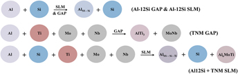
The XRD patterns of the gas-atomized Al–12Si and TNM powders along with the Al–12Si and TNMC with 20 vol% TNM SLM samples are shown in Fig. 1. The Al–12Si GAP shows diffraction peaks of α-Al [face centered cubic structure, Pearson symbol: cF4, and space group: Fm3m (Ref. Reference Wang, Prashanth, Scudino, He, Zhang, Li, Stoica, Vaughan, Sordelet and Eckert42)] whereas the peaks of Si are not distinctly visible. The TNM powder shows the presence of the following intermetallic phases: AlTi3 [hexagonal structure, Pearson symbol: hP8, and space group: P63/mmc (Ref. Reference Huneau, Rogl, Zeng, Schmid-Fetzer, Bohn and Bauer43)] and MoNb [body centered cubic structure, Pearson symbol: cl2, and space group: Im3m (Ref. 44)]. The Al–12Si SLM samples display the crystalline peaks of α-Al along with weak Si peaks, similar as those observed for the Al–12Si powder. However, the intensities of the α-Al peaks (111) and (200) are reversed with respect to the Al–12Si powder. The XRD pattern of the Al12–Si–TNM SLM sample shows the presence of α-Al peaks and the peaks of Si are weak. The Si peaks are not as distinct as in the case of the Al–12Si SLM samples. However, in contrast to the Al–12Si SLM sample, there is no texture observed between the α-Al peaks (111) and (200). Additional peaks from the Al6MoTi phase [orthorhombic structure, Pearson symbol: oC112, and space group: Cmc21 (Ref. Reference Gulay, Daszkiewicz and Shemat45)] are also observed.

FIG. 1. XRD patterns (λ = 0.17889 nm) of the Al–12Si and TNM powders and the unreinforced Al–12Si and Al–12Si–20 vol% TNMC samples produced by SLM.
The microstructure of both the unreinforced Al–12Si and the TNMC composites prepared by SLM are shown in Fig. 2. The low magnification SEM images [Figs. 2(a) and 2(b)] of the Al–12Si SLM samples do not reveal any characteristics except for the nonuniformity in the microstructure and the laser tracks or track overlaps [Fig. 2(a)]. Track overlaps are the regions, where the melting takes place twice between two laser tracks. At higher magnification [Fig. 2(c)] the Al–12Si SLM sample displays a cellular microstructure (cell size varying between 500–1000 nm) with the Si phase present along the cellular boundaries (thickness ∼200 nm). Reference Prashanth, Scudino, Klauss, Surreddi, Löber, Wang, Chaubey, Kühn and Eckert14 Moreover, the microstructure is nonuniform with an elongated morphology along the track overlaps and circular morphology outside of the track overlaps. Reference Prashanth, Scudino, Klauss, Surreddi, Löber, Wang, Chaubey, Kühn and Eckert14 Such an anisotropic structure is a characteristic for SLM samples. Reference Schwab, Prashanth, Löber, Kühn and Eckert46–Reference Li, Wang, Saunders, Suvorova, Zhang, Liu, Fang, Huang and Sercombe48 On the other hand, the microstructure of the TNMC is completely different. Figures 2 (d)–2(f) suggest that the reinforcement is distributed in the form of irregularly shaped dendrites and particles, with an average width of 482 ± 68 nm and 1.75 ± 0.32 µm length. It can also be observed that the distribution of the reinforcement is not uniform throughout the sample, with a coarser structure on the laser tracks and finer cells along the core. EDX analysis (the corresponding point and area scans are not shown here) indicates that the dendrite shaped reinforcement are rich in Al, Ti, and Mo, corresponding to the Al6MoTi phase observed by XRD.

FIG. 2. SEM images showing the microstructure of (a–c) unreinforced Al–12Si and (d–f) Al–12Si–TNMC produced by SLM.
B. Mechanical and tribological properties
The hardness of the Al–12Si SLM samples is 1.28 ± 0.02 GPa, whereas the TNMC exhibits an average value of 2.42 ± 0.35 GPa. The samples were checked for density before the compression tests were carried out. Both the Al–12Si and TNMC samples have a relative density of around ∼99.5% and hence they are considered to be sound for the compression tests. The room temperature compression test results of both Al–12Si and TNMC SLM samples are displayed in Fig. 3. The Al–12Si SLM samples show a yield strength of 283 ± 3 MPa and an ultimate compressive strength of 475 ± 6 MPa. The Al–12Si samples do not break up to 60% strain; hence, the compression tests were stopped once the ultimate compressive loads are reached. On the other hand, the TNMC samples exhibit an yield strength of 420 ± 4 MPa and an ultimate compressive strength of 636 ± 3 MPa. However, the TNMC samples break after ∼6% deformation under compression.

FIG. 3. Compressive room temperature true stress–strain curves of the Al–12Si and Al–12Si–TNMC samples produced by the SLM process.
Figure 4(a) furnishes the wear results of both Al–12Si SLM and TNMC samples. At 10 N load the wear rate of the Al–12Si SLM samples is ∼1.31 × 10⁻¹² m3/m which is three times higher than the values observed for TNMC (∼0.34 × 10⁻¹² m3/m). This suggests that the Al–12Si–TNMCs are more resistant to sliding wear. The composite samples were also tested under different loading conditions varying from 10 to 50 N. With increasing load, the wear rate of the TNMC sample increases from ∼0.34 × 10⁻¹² m3/m at a load of 10 N to ∼2.08 × 10⁻¹² m3/m at a load of 50 N. It can also be observed from Fig. 4(a) that the wear resistance follows a negative exponential pattern when the load increases in the sliding wear test. Figure 4(b) shows the normalized wear of the TNMC material under different loading conditions as a function of the sliding wear time. As expected, the wear of the composites increases with increasing time for all loads; however, some differences are observed between the wear curves under different loading conditions. The wear curves show a linear pattern for both 10 and 20 N loads, respectively, whereas the curves are no longer linear when the load increases beyond 20 N. Instead the curves show an irregular wear behavior during the measurement time of 30 min.

FIG. 4. (a) Wear rate and wear resistance of Al–12Si SLM samples at 10 N and Al–12Si–TNM SLM composites as a function of different loads from 10 to 50 N. (b) Wear of Al–12Si–TNM SLM composites at different loads (from 10 to 50 N) as a function of time.
The wear scars on the surface of both the Al–12Si and TNMC SLM samples tested at a load of 10 N are shown in Fig. 5. The arrows in the figures represent the sliding direction. The Al–12Si SLM samples [Figs. 5(a) and 5(b)] show wear scars along the sliding direction, which is typical for a wear surface along with the presence of plowing grooves. It also shows the signs of delamination cracks; however, there is not significant delamination observed except for deep wear scars and plowing. Figure 5(b) also shows the presence of oxides (confirmed using EDX point scan analysis, not shown here). On the other hand, the TNMC SLM sample surface shows wear tracks that are shallow [Figs. 5(c) and 5(d)] compared to the wear scars of the Al–12Si SLM samples. No significant plowing grooves were observed for the TNMC samples. The higher magnification image [Fig. 5(d)] shows the presence of delamination cracks and a partially delaminated layer along with some oxide particles.

FIG. 5. SEM images showing the wear tracks after sliding wear test for the (a and b) Al–12Si and (c and d) Al–12Si–TNM SLM samples.
Figure 6 presents the wear scars of the TNMC composite samples subjected to different loading conditions (10, 30, and 50 N). As explained before, the TNMC samples tested at 10 N load show shallow wear scars and there are no significant plowing besides some cracks and a partially delaminated layer [Figs. 6(a) and 6(b)]. Increasing the load from 10 to 30 N causes deeper wear scars and plowing grooves [Figs. 6(c) and 6(d)] compared to the wear scars of the sample tested at 10 N. The wear surface seems to be nonhomogeneous with regions of both deep wear tracks and shallow wear tracks. Also, delamination cracks and subcracks are observed in Fig. 6(d) along with oxide particles. With further increase of the load to 50 N, the nonhomogeneity in the wear surface increases with deeper wear scars in some selected regions and shallow wear tracks in the other regions [Figs. 6(e) and 6(f)]. Delamination of the layer along with particle pullout can be observed from Fig. 6(f) along with the presence of delamination cracks and selective oxidation.

FIG. 6. SEM images of the wear tracks after sliding wear test for the Al–12Si–TNMCs as a function of load (a and b) 10 N, (c and d) 30 N and (e and f) 50 N.
IV. DISCUSSION
A. Phase formation
A detailed characterization of the Al–12Si SLM samples can be found elsewhere. Reference Prashanth, Scudino, Klauss, Surreddi, Löber, Wang, Chaubey, Kühn and Eckert14 Hence, only requisite information about the Al–12Si SLM samples is presented here to have a comparison with that of the TNMC samples. The XRD patterns of the Al–12Si GAP and SLM samples do not show distinct peaks of Si, which may be attributed to the large degree of supersaturation of Si in Al. Reference Prashanth, Scudino, Klauss, Surreddi, Löber, Wang, Chaubey, Kühn and Eckert14 The lattice parameter of α-Al, evaluated using the Rietveld profile refinement method Reference Rietveld49 is 0.40513 and 0.40508 nm for Al–12Si GAP and SLM samples, respectively. This confirms the formation of a supersaturated solid solution of Si in Al and the amount of free residual Si in these samples is less than 1 wt%. Reference Prashanth, Scudino, Klauss, Surreddi, Löber, Wang, Chaubey, Kühn and Eckert14 Moreover, the α-Al peaks are broader in the SLM samples, which are correlated with a fine crystallite size (118 ± 3 nm for the SLM sample and 136 ± 5 nm for the GAP powder). The reversal of the peak intensities between the (111) and (200) peaks of α-Al in the Al–12Si SLM samples points to the development of the texture in the SLM material. Reference Prashanth, Scudino, Klauss, Surreddi, Löber, Wang, Chaubey, Kühn and Eckert14 The TNMC SLM samples exhibit a lattice parameter of 0.40511 nm for α-Al, which is different from the lattice parameter of α-Al observed in the Al–12Si SLM samples. This marginal lattice parameter increase can be ascribed to a smaller amount of Si in α-Al. However, the amount of free residual Si is calculated to be ∼1 wt%, which is similar to that of the Al–12Si SLM samples.
The TNMC samples show the presence of the Al6MoTi phase but no hints for the formation of TiAl3 and MoNb phases suggesting a phase transformation from TiAl3 and MoNb to Al6MoTi in the presence of the Al–12Si matrix. A similar phase transformation sequence has been observed for the Ti–Al alloys subjected to intense ion beam irradiation, Reference Mingjuan, Qingye and Weibo50 where Mingjuan et al. observed changes in the local composition of the melt, whereby an increase in the chemical concentration of Al and Mo and a decrease in the Ti concentration lead to the formation of the Al6MoTi phase, making this phase thermodynamically stable. Reference Mingjuan, Qingye and Weibo50
By considering the increase in the lattice parameter of α-Al and the formation of the Al6MoTi phase, the following scenario can be proposed. During SLM of the TNMC composites, both the Al–12Si and TNM powders are expected to melt due to the high energy density of ∼55 J/mm3, which is applied for producing a defect free sample. The degree of constitutional undercooling increases under high energy input, which leads to the formation of a supersaturated solid solution. In the present melt, the Si from Al–12Si contributes to form a supersaturated solid solution of Al. Reference Prashanth, Damodaram, Scudino, Wang, Prasad Rao and Eckert51 However, having a similar amount of free residual Si in both the TNMC SLM and Al–12Si SLM samples and considering the formation of the Al6MoTi phase, it can be postulated that the melt becomes deficient in Ti due to the diffusion of some Ti into Al. Also, it is believed that during the laser melting process, mixing of the melt takes place due to the convection phenomena. It has been reported that the convection pattern of the fluid flow during the laser melting process is directed radially outward with the formation of symmetric vortices on the cross-section of the melt pool. Reference Yuan, Gu and Dai52 Such through mixing of the melt pool facilitates Ti to be in contact with Al and the high degree of constitutional undercooling results in the formation of a supersaturated solid solution of both Ti and Si in Al (AlSS–Si–Ti) as demonstrated in Fig. 7. Such a reaction will consume Ti from the TiAl3 phase and the deficiency in Ti will lead to the formation of the Al6MoTi intermetallic phase.

FIG. 7. Schematics illustrating the formation of supersaturated solid solution of Si in Al and Ti and Si in Al for Al–12Si SLM and Al–12Si–TNM SLM composites.
B. Mechanical properties and wear mechanism
The Vickers microhardness of the TNMC SLM samples shows a greater deviation from the average hardness (0.35 GPa) as compared to the Al12–Si SLM samples (0.02 GPa) due to the significant difference in the hardness between the two phases AlSS–Si–Ti and Al6MoTi observed in the TNMC composites. The hardness of the AlSS–Si–Ti phase is 1.62 ± 0.03 GPa and Al6MoTi exhibits a hardness of 3.95 ± 0.02 GPa, which is similar to TiAl produced by electron beam melting. Reference Murr, Gaytan, Ceylan, Martinez, Martinez, Hernandez, Machado, Ramirez, Medina, Collins and Wicker53 Such high strength reinforcement helps to increase the hardness of the composite significantly. The TNMC samples show yield and ultimate compressive strengths, which are ∼140 and ∼160 MPa, respectively, higher than the corresponding values of the Al–12Si SLM samples. On the other hand, the TNMC samples break at ∼6% total strain under compressive deformation, whereas the Al–12Si SLM samples do not fracture until 60% of deformation. This shows that the TNM reinforcement helps to improve the strength of the composite but renders the composites extremely brittle.
During the sliding wear tests, the counter surface may induce a high strain level at the contact surface of the sample. Reference Suh54 Such a high strain level will eventually lead to cracks and subsurface cracks, as observed for the Al–12Si SLM samples. However, these cracks are not deep enough for delamination due to the resistance exerted by the sample surface. Also, the sliding of the sample against a counter disc causes a strong temperature rise along the sample surface as well as on the counter disc. The temperature rise leads to preferential oxidation of the sample surface (as observed by EDX analysis, not shown here). Reference Dwivedi55,Reference Liu, Asthana and Rohatgi56 Hence, the wear of Al–12Si SLM samples takes place through plowing, partial delamination and oxidative wear. Reference Liu, Asthana and Rohatgi56–Reference Zhang and Alpas58 This scenario also holds for the Al–12Si–TNMCs. On the other hand, the Al–12Si–TNMCs are prepared by SLM at 10 N wear and also through partial delamination. The wear rate remains linear up to a testing time of 30 min. When the load increases from 10 to 30 N and beyond, the wear rate seems to have a different behavior in the 30 min testing time regime [Fig. 4(b)]. The samples experience a maximum wear rate for the initial ∼5 min and with increasing time, the wear takes place at a decreased rate (up to ∼20 min). With further increasing time, the wear rate decreases. This might as well be correlated with the nonuniform wear surfaces observed in Figs. 6(c)–6(f).
Based on the microstructure of the Al–12Si–TNMCs, the wear rate data (Fig. 4) and the wear scar images (Fig. 6), the following wear mechanism can be proposed. The surface of the composites consists of AlSS–Si–Ti and Al6MoTi phases. As already discussed, the Al SS–Si–Ti phase has a hardness of 1.62 ± 0.03 GPa, whereas a hardness of 3.95 ± 0.02 GPa was found for the Al6MoTi intermetallic phase. During wear, the soft AlSS–Si–Ti gets worn out of the surface (marks of plowing) and the Al6MoTi intermetallic phase contributes to its resistance (which is termed as Region I—Fig. 8). At the initial stages (<5 min) both the AlSS–Si–Ti and Al6MoTi phases are in contact with the counter disc causing the sliding wear. With increasing time, as the AlSS–Si–Ti phase wears out, the amount of Al6MoTi along the surface increases and it decelerates the wear rate. Once the Al6MoTi phase is devoid of the surrounding soft AlSS–Si–Ti phase, the pull out of the Al6MoTi particles is inevitable as illustrated in Fig. 8. In this phase (Region II), the wear rate is influenced by both the AlSS–Si–Ti and Al6MoTi phases. The AlSS–Si–Ti phase contributes to the wear in the form of plowing (and partial delamination) and the pull out of the Al6MoTi phase also takes place simultaneously. With increasing time, the amount of AlSS–Si–Ti phase which is in contact with the counter disc drops significantly and as the amount of Al6MoTi phase further increases, thus reducing the wear rate more (Region III).

FIG. 8. Plot showing the three different rates of wear observed during the wear of the Al–12Si–TNM SLM composites at 40 N loads as a function of time and schematics illustrating the mode of wear taking place in the three regions.
V. SUMMARY
Al–12Si (80 vol%)–TNM composites were successfully prepared by the SLM process. Structural and microstructural characterization reveals chemical reactions between the matrix and the reinforcement leading to the formation of AlSS–Si–Ti and Al6MoTi phases. The formation of the Al6MoTi phase is promoted by the devoid of Ti in the melt, which is due to the supersaturation of Al with Ti. The compression test results show that the composites have improved strength levels compared with the Al–12Si matrix. However, the composites are less plastically deformable and break at ∼6% total strain under compression. The composite also show an improved wear resistance compared with the unreinforced matrix and exhibit similar wear mechanisms. However, the surface of the composite at higher loads shows uniform wear scars which might be due to partial delamination that occurred from particle pull out. The wear rate of the composites increases with increasing load from 10 to 50 N. At lower loads (10 and 20 N), the composites show uniform wear throughout the 30 min test time. When the load increases beyond 30 N, nonuniform wear rates are found for the composites. The maximum wear rate is observed at the early stages and it decreases after 5 min of continuous sliding. The results demonstrate that composites with metallic reinforcement and superior properties can be processed using the SLM process.
ACKNOWLEDGMENTS
The authors thank Harald Merker for technical assistance. P. Wang would like to acknowledge the fellowship support from the China Scholarship council.


 Open access